Introduction
The Context Driving Speed Limit Alert system (CDSLA) has developed by the integration of GPS and GIS for collecting En route traffic data from a probe vehicle. This system has been further integrated with the engine management system of a vehicle to provide time-tagged data on GPS position and actual speed, distance travelled, acceleration, fuel consumption, engine performance, and air pollutant emissions on a second-by-second basis,
GPS devices are positional speedometers, based on how far the device has moved since the last measurement. The algorithm also uses the Doppler shift formula in the pseudo range signals from the satellites. It should also be noted that the speed reading is normalized, and is not an instant speed.
All GPS/GIS tracking systems use the Global Positioning System to determine and regularly record the location of an object and it can be used to calculate the targeted objects speed, and the CDSLA Receive the vehicles speed from. GPS speed calculations are more accurate than a vehicle’s speedometer since it is not affected by the same inaccuracies, including the vehicle’s wheel size or drive ratios. It is dependent however on GPS satellite signal quality but with the use of moving average calculations any errors are minimal. we have to mention that Vehicle speedometers also require calibration to maintain perfect accuracy as general wear and tear, changing wheel sizes, and the manufacturers own ‘erring on the side of caution’ and setting the speedometer to read higher than the actual speed, all contribute to inaccuracies.
Generally most manufacturers appeal a 0.1 MPH allowance with speed readings, however will go as far to say a 0.5MPH inaccuracy is possible, to take into account for any satellite signal variations beyond their control.
Transportation data, in common with many other data sets in civil engineering and the social sciences, often have spatial attributes. For example, traffic counts come from specific sites, travel time data refer to particular routes, and origin–destination data apply to a given area. [17] Generally, these fall into the following areas: tracking, mapping, navigating, locating and obtaining precise timing [8].
Over time, the GPS system is constantly evolving and it works anywhere in the world and the information is available all day time. Luckily the government does not impose subscription fees to use the system. [9]
A key element of the CDSLA is the use of GPS data to determine locations, for both static observations and dynamic recording of vehicle positions over time. The GIS takes on the central role in data management, in terms of data entry and integration, data management, and some aspects of data analysis and display. [17]
The GPS is a network of satellites placed into orbit by the U.S. Department of Defense. [8] But now many countries involved in similar projects and using their own system. Receivers can catch the signals at least from these three satellites to guarantee the accuracy of signals caught from them. GSM (Global System for Mobile communications) technology is used to transmit this and display the geographical position of the vehicle at the base station. [13]
The integration of GIS-GPS technologies can be achieved in many ways. GIS-GPS integration has numerous applications in various fields [1,3]. One of them is vehicle tracking, which is one of the most developing fields; by vehicle tracking in addition we mean vehicle speed check too and alert system CDSLA [8]. In this paper, we would like to present the CDSLA depending on vehicle tracking and speed check system for vehicle as an object navigation, which is depends on online mode through wireless communication.
GIS and GPS technology have brought some breakthrough in the area of transportation monitoring and management. One of the most useful applications is a vehicle tracking system to determine and trace the position of the mobile vehicle [1] and to avoid road congestions, and avoid traffic violations. The system locates vehicles using GPS satellites, GPS receivers and other auxiliary equipments display the geographical coordinate of the vehicle position on a digital road map of the monitoring system [10].
Conventional database systems cannot make much use of the spatial or locational attributes of a data set, other than hold reference details for it. Geographical Information Systems (GIS), on the other hand, can absorb a database, relate its spatial attributes to maps of the region, and offer spatial integration with other pertinent databases for that region.[17]
The digital map is a vector-typed spatial database to manage topologically the spatial objects which correspond to entities existing in the real world. The map used in the vehicle tracking system contains a variety of geographic and traffic-oriented resources and rules; and keeps the up-to-date information on roads like the speed limits, buildings, traffic signals, road constructions and associated transportation facilities. In case of a distributed environment which each monitoring station needs to possess its own spatial database, essential to the entire system, is to guarantee data integrity or data consistency among all the database holders [7].
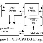
This paper describes the design and implementation of the GPS-GIS database Integrator depending on client/server technology for spatial data processing crucial to measure the speed of a mobile vehicle and tracking its position. And offers alternative text coordinates of a spatial database. A data caching technique is introduced in order to enhance the transmission efficiency between both sides. Also, technical issues of GPS, DGPS (Differential GPS) and wireless communication fields are presented to reach the proposed goal [11,14].
Some systems can pinpoint location within less than 1 meter. A GPS receiver needs information from at least two satellites to calculate a 2-D position (latitude and longitude), but with four or more satellites, a 3-D picture (latitude, longitude, and altitude) can be obtained and be more accurately. After that, speed, bearing, distance to a destination and other information may be calculated. With special software, an animated picture may be imposed over a street map or satellite image or displayed in a report format.
GIS-GPS DB Integrator
Spatial data processing based on a client/server technology may be a methodology well-suited for tackling this burdening problem. The approach employs a server and multi-clients architecture in which the server exists in a control center and each client falls under one of monitoring stations [5,15]. available in any public transportation agents or private companies or Traffic Control Police Station. The proposed structure may achieve the data integrity and cost-effective maintenance of database, since the server manages exclusively the spatial data and deals with a series of processes requested from the client side. One of the big advantages is that if the server and clients are connected on-line, the server would obtain the traffic information occurring on the streets, the base station obtains the traffic information from the clients in text format corresponding the spatial data which stored in spatial database, the clients benefits those without any interconnection to other information channels.
The integration of the various data collection modules in the vehicle is a major task facilitated by the use of GIS. The data collection modules include differential GPS (for time-based location, speed, and direction of travel), and on-board vehicle data like speed, acceleration, fuel consumption, engine performance, and emission rates. [1] The GIS system makes strong use of GPS for real-time data collection, and integration with a radio communications system allows for the real-time tracking of a fleet of probe vehicles, as well as post-processing of the on-road data. [17]
The integration of GPS technology into GIS activities can be achieved through a variety of means. These range from the transfer of data from GPS systems, for the building of new spatial database, to the complete integration of GPS technology into existing GIS systems, to conduct spatial analysis directly in the field [6]. The GIS-GPS integration can be done in three categories: Data-focused integration, Position-focused integration, Technology-focused integration.
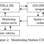
Monitoring System Integration
In the suggested client/server structure, a Synchronized Monitoring System in control center plays an active role, to settle the inconsistent data and consequential maintenance resulting from the situation in which the regional dispersed monitoring stations share the same spatial data for their own purpose of transport management. The spatial DB server is to keep the periodically updated road map that basically sends the data by peculiar units of layers according to request of clients. The client systems of public agencies/institutions or private enterprises closely related with the transportation affairs utilize those data immediately transferred into main-memory in the powerful PC-based system [5,19,12].
We apply a spatial data caching (integrator) technique to the client/server system in order to decrease the time period of transmission and the size of data downloaded, and eventually to raise the system efficiency to be more Synchronized. At initial booting time of the client system, a main part of monitoring areas may be activated through cache memory, and then those cached areas are brought up instantly at the speed of memory access without giving any burden to the server. Whenever a request for other areas and layers is made, the server replies by following the usual procedures and sends the corresponding data. Empirically, the desirable size of cache is about twice as much as the main-memory of the monitoring system.
Satellite’sSignal Travel
A GPS receiver accepts the signals involving the satellite’s clock and orbit information of each one of the applicable satellites and calculates the difference between the receiver clock at the signal’s reception time and the satellite clock at its transmission time. The time difference derives a distance from the receiver to each one of satellites and then the location of each satellite can be elicited from its orbit information. Finally, the location of the receiver is computed. The signal travels to the ground at the speed of light. Even at this speed, the signal takes a measurable amount of time to reach the receiver. The difference between the time when the signal is received and the time when it was sent, multiplied by the speed of light, enables the receiver to calculate the distance to the satellite. D = t1-t2 *LS where LS is Light Speed, and d is distance of the satellite, and t1,t2 are time of Transmition and the time of receiving the signals. To make this measurement as accurate as possible, the GPS navigation signals are specially designed to make it easy for GPS receivers to measure the time of arrival and to allow all the satellites to operate on the same frequency without interfering with each other. To calculate its precise latitude, longitude, and altitude, the receiver measures the distance to four separate GPS satellites. By using four satellites, the receiver calculates both its position and the time and doesn’t need an expensive atomic clock like those on the satellites.
A GPS receiver monitors microwave signals from the orbiting satellites. These signals contain the time of transmission and the position of the satellite, and these signals are corresponding to the signals caught from the receiver of the mobile vehicle by the satellite, and each signal is known from which receiver is delivered and it reflects the signals come from the vehicles. The receiver analyzes these signals by using the travel time of the signals and positions of the transmitting satellites to trilateral position. At least two signals are necessary to find the position, and four signals are necessary for a definite position using the GPS system.
GPS coordinate data is fed into the unit’s database of road information, indicating your location on a stored map. This database and location information is also usually analyzed to provide directions to a given destination.
Speeds are updated at short intervals to maintain accuracy at all times. It uses frequent calculations to determine the vehicle’s speed.
While the object is traveling from point to point, its coordinates are changing through time, and the system can register these coordinates, and use it to monitor the object. L1=(x1, y1) the first position of the vehicle, L2= (x2, y2) the Second position of the vehicle,… Ln= (xn, yn) the n position of the vehicle. D1= L2- L1 where D1 is the first distance the vehicle mileage. D2=A3-A2 where D2 is the second distance the vehicle mileage, Dn= Ln– Ln-1 where Dn is the n distance the vehicle mileage.
The time period between sending two signals to the vehicle receiver from the first and second satellite is t1=S1 t2- S1t1 from the first and t2=S2 t2- S2t1 from the second. The speed in period between any two signals from the first satellite is S1 = D1/t1, and the in period between any two signals from the second satellite is S2 = D2/t2, the average speed of the object in a known period time according the first satellite is equal to:
s1 = ΣDs1/Σts1 where Ds1 is the distance mileage according the first satellite, and ts1 is the period of time
taken by the object for undertaken mileage.
The average speed of the object in a given time according to the second satellite is equal to:
s2 = ΣDs2/Σts2 where Ds2 is the distance mileage according the second satellite, and ts2 is the period of time taken by the object for undertaken mileage.
The average speed of the mobile object in a known period of time according to the first and second satellites is equal to:
s = s1+s2/2
where Ds2 is the distance mileage according the second satellite, and ts2 is the period of time taken by the object for undertaken mileage.The average speed of the mobile object in a known period of time according to the first and second satellites is equal to:
Features of CDSLA
We can take in our consideration many additional features to help the system clients to fulfill their needs; some of these features are as the following:
- Alarm the client when he exceeded the speed instantly according the road context.
- Alarm information can be transmitted to the central base station of CDSLA.
- The drivers can query traffic situation and congestions on rout from the station.
- The client can receive Messages from the Central station of CDSLA on various media.
- Automatic registration of client speed traffic violation.
- Automatic registration of locations the vehicles client crossed over.
- Registration of client’s average speed in a homogeneous speed through.
Base Station of VSC and CDSLA
The Base Station includes a GSM Module and Web Server that allows the controller to view the vehicle on a Geographic map. Multi layer in-depth maps of each city are available and the position of CDSLA of the vehicle is displayed on these maps. The Base Station has an in-built Web Server. The position CDSLA information received from each vehicle is stored in the database. And according to its location the system calculates the current speed and registers it in database simultaneously of the Commission traffic control in the base station according to the vehicle ID which is saved in the vehicle receiver and it is transmits with signals. The system transmitted a message to the vehicle if its speed exceeded the limits fixed for that rout.
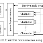
System Wireless Communication
As you notice, the Context Driving Speed Limit Alert needs to be channeled or directed by a wireless communication link from the receiver of the vehicle to the monitoring station CDSLA. Beyond this kind of immediate demand, the advent of wireless era accelerates the nationwide construction of various wireless networks. Currently, a conventional private network, a TRS (Trunked Radio System) network, is a complex type of computer–controlled two-way radio system that allows sharing of relatively few radio frequency channels among a large group of clients. Instead of assigning, for example, a radio channel to one particular organization at a time. Each radio transceiver contains a microcomputer to control it. A control channel coordinates all the activity of the radios in the system. The control channel computer sends packets of data to enable one group to communicate together, regardless of frequency.
A cellular network, a satellite network and a data packet network may be a candidate for the application.
Now, let us briefly examine the characteristics of each one. A private network enables user to utilize its unique radio-frequency, but it restricts severely the number of vehicles to be monitored because its circuit switching prevents other users from accessing the primitive line [4]. TRS gives a wide range of frequencies which a large number of users can share. Users enjoy a high rate of connections, a good quality of data types and more a reasonable cost of communication. Recently, researches on digital TRS are actively under way in order to overcome some restraints of the analogue method. A satellite network has a extensive coverage for the service. Its disadvantage is, however, a low rate of data transmission in addition to expensive receiver equipments.
A data packet network is considered applicable in that a message is transmitted by a series of short packets and its packet switching sequentially increases the network utilization. Besides, it makes retransmission of lost data possible when an error happens during the transmission. Actually, in case of the client Context Driving Speed Limit Alert which data transmissions are frequently occurring in a short term, the data packet may be a effective means of communication. In the data packet network, the messages are exchanged between the receiver and the station through TRS. A unique identification number assigned to each modem tells the location of a specific vehicle that carries it.
CDSLA Configuration
The CDSLA is completely modular in design. It is made up of three main parts including the satellite as one of them: The Mobile Vehicle Unit (receiver) and The Fixed Base Station or monitoring station (receiver and controller). And it includes next listed units:
- GSM Module.
- GPS Module.
- Controller Module.
- Storage module (optional).
- Display/Entry module.
- Additional Sensing modules (temperature, accident, speed, etc.)
The CDSLA unit is configured around main Controller module, which executes the software to configure and control the GPS receiver, GSM module, and IO Ports. This unit is to be fixed in the vehicle, with appropriate GPS and TRS.
The GPS receiver detects the position and provides it to the Controller module. The
Controller module converts the received data and sends it to the central station using SMS or another media to the spatial database [18].
As mentioned earlier, the server system is composed of relational DBMS, Oracle and GIS engine, SDE installed on the top of UNIX operating system. Each client system available in the monitoring stations keeps a copy of the application program. There is an integrator module located between the two databases to coordinate their contents and to response the controller. The future application program for the CDSLA will consists of four main software modules.
- Information Management.
- Map Control.
- Vehicle Operation Control.
- Message Management.
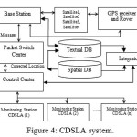
The components to form the CDSLA are illustrated in Figure 4. As you see, each client vehicle transmits GPS data related to its location through network which is hierarchically made up of base-stations, local switches, and a packet switch center. The control center hands over the data from the packet switch center to a corresponding monitoring station via a dedicated line. On the other hand, the DGPS base station dispenses the information indispensable to the database in the base station. For correcting the inaccurate location of vehicles, following the reverse order of paths shown in the packet network [2,16]. Here, another dedicated line needs to be installed between the DGPS station and the packet switch center. Finally, vehicles transmit the current location to the monitoring station.
Implementation
To conduct an experiment for the CDSLA, we choose some routs as a sample, to simplify the spatial database. The main center and the monitoring stations build up the client/server structure through the dedicated lines of high speed. Normally, the coordinate system to represent the position by GPS is WGS-84(World Geodetic System) which is not suitable for display on the plane map. WGS is a standard for use in cartography, geodesy, and navigation including by GPS. It comprises a standard coordinate system for the Earth, a standard spheroidal reference surface we, therefore, develop a program to convert it into TM coordinate in order to achieve successful mapping. The information as to a vehicle’s location is kept in a log file which usually contains an ID number of the vehicle, receiving time of GPS’s location data, the converted TM coordinate, direction of the vehicle and so on. Later on, we can record track history of paths from this log data. In addition to the location data, the client program facilitates exchange of the messages associated with an intended service by using function keys in the receiver.
The digital map includes center lines within the roads to take advantage of a map-matching technique applied to the vehicle navigation frequently. Based on the condition that “the land vehicle is almost always running on the roads”, map-matching is a mechanism to hold the positioning accuracy even in cases that the vehicle experiences some difficulties in receiving the signals, or seems to be run out due to the error of the digital map. Separately from center lines, nodes point to intersections are involved in the map data [7]. The information of center lines and nodes offer a way to find out the shortest path from origin to destination. And some other information we use to calculate congestion [4].
Conclusion
Big cost that could be incurred by companies, individuals and States from Accidents and non-disciplined behaviors Calls for serious Decision. The possibility of accidents as well as infringement notices or demerit points. Speeding alerts can be setup to record either speeds in excess of the posted speed limit, or simply if a certain speed is reached. Since employers know that speeds calculated by GPS devices are not only more accurate than a vehicle’s speedometer but also lower, it gives employees no excuse to be caught driving at unsafe speeds. Through a combination of regular reporting and driver coaching, fleet owners can make sure they are doing everything in their power to improve the safety of their staff and other road users.
In this paper, core issues have been described regarding GIS, GPS and wireless communication networks to be evolved during the development
of the land CDSLA The implemented method has been also presented with client/server solution in textual road coordinates database and spatial data processing, and a data-caching (data-Integrator) technique which is suitable for data retrievals in reasonable response time.
The land CDSLA is an application programs that we can develop to construct the national logistics network. As a result of implementing a prototype system, the data integrity and the cost-effective maintenance of spatial database and textual road coordinates database can be fulfilled. This system it is followed, saying prevention is better than cure.
References
- S.Kiruthivasan, C.Madan Deepakumar, Decision Support System For Call Taxi Navigation Using GIS-GPS Integratio,
- Charles Vlcek, Patricia Mclain, and Michael Murphy, “GPS/Dead Reckoning for Vehicle Tracking in the Urban Canyon Environment”, Trimble Navigation, Ltd., 1993.
- D. J. Maguire, “An Overview and Definition of GIS”, Geographical Information Systems, Vol. 1, pp. 9-20, 1992
- A.T.Issa, “Online Transport Monitoring System by the Integration of GPS and GIS”, ORIENTAL JOURNAL OF COMPUTER SCIENCE & TECHNOLOGY, Vol. 8, No(1):Pgs. 01-08, 2015
- O. Guenther and A. Buchmann, “Research Issues In Spatial Databases”, SIGMOD RECORD, Vol. 19, No. 4, pp. 61-68, 1990.
CrossRef
- R. H. Guting, “An Introduction to Spatial Database Systems”, VLDB Journal, Vol. 3, No. 4, pp. 357-399, 1994.
CrossRef
- Robert L. French, “Land Vehicle Navigation and Tracking”, Global Positioning System : Theory and Applications, Vol. 164, pp. 275-301, 1996
- Ronald Braff, “Applications of the GPS to Air Traffic Control”, Global Positioning System : Theory and Applications, Vol. 164, pp. 327-374, 1996
- Steven E. Shladover, “Research and Development Needs for Advanced Vehicle Control Systems”, IEEE Computer Society, 1993.
- W. Richard Stevens, UNIX Network Programming, Prentice-Hall International, Inc., pp. 258-277, 1994
- ESRI, Introduction to SDE, 1995
- 27sep2010 http://searchmobilecomputing.techtarget.com/definition/Global-Positioning-System
- 2005B. C. Ooi and K. J. McDonell, “Extending a DBMS For Geographic Applications”, Proc. of IEEE Data Engineering, pp. 590-597, 1989.
CrossRef
- 27sep2010 http://www.gisdevelopment.net/tutorials/tuman004.htm
- 27sep2010 http://hyperphysics.phy-astr.gsu.edu/Hbase/gpsrec.html
- 27sep2010 http://www.trimble.com/gps/index.shtml
- Michael A.P, Taylor, E. Woolley, Rocco Zito, integration of GPS and GIS for traffic congestion studies, University of South Australia, sep. 2000
- 27sep2010 http://www.nasm.si.edu/exhibitions/gps/work.html
- 27sep2010 http://electronics.howstuffworks.com/gadgets/travel/gps.htm

This work is licensed under a Creative Commons Attribution 4.0 International License.