Krishna*, Shashi Yadav and Nidhi
Computer Science and Engineering, Maharshi Dayanand University, Haryana, India.
Article Publishing History
Article Received on :
Article Accepted on :
Article Published :
Article Metrics
ABSTRACT:
The objective of this paper is to control the railway tracks by using anti-collision techniques. The model of railway track controller is designed by using 8952 microcontroller to avoid railway accidents. When we go through the daily newspapers we come across many railway accidents occurring at unmanned railway crossings. This is mainly due to the carelessness in manual operations or lack of workers. And also the collision of two trains due to the same track. This model is implemented using sensor technique. We placed the sensors at a certain distance from the gate detects the approaching train and accordingly controls the operation of the gate. Also an indicator light has been provided to alert the motorists about the approaching train.
KEYWORDS:
Microcontroller; LED; Anti collision device; track switching
Copy the following to cite this article:
Krishna, Yadav S, Nidhi. Automatic Railway Gate Control Using Microcontroller. Orient. J. Comp. Sci. and Technol;6(4)
|
Copy the following to cite this URL:
Krishna, Yadav S, Nidhi. Automatic Railway Gate Control Using Microcontroller. Orient. J. Comp. Sci. and Technol;6(4). Available from: http://www.computerscijournal.org/?p=2860
|
Introduction
Railway safety is a crucial aspect of rail operation over the world. Railways being the cheapest mode of transportation are preferred over all the other means. When we read newspaper, we come across many railway accidents occurring at unmanned railway crossings. This is mainly due to the carelessness in manual operations or lack of workers. And also the collision of two trains due to the same track. This model deals with two things. Firstly, it deals with the reduction of time for which the gate is being kept closed. And secondly, to provide safety to the road users by reducing the accidents that usually occur due to carelessness of road users and at times errors made by the gatekeepers. To avoid the accidents, sensors placed at some distance from the gate detect the departure of the train. The signal about the departure is sent to the microcontroller, which in turn operates the motor and opens the gate. Thus, the time for which the gate is closed is less compared to the manually operated gates since the gate is closed depending upon the telephone call from the previous station. Also reliability is high, as it is not subjected to manual errors.
Concept
Now a days, India is the country which having world’s largest railway network. Over hundreds of railways running on track every day. As we know that it is definitely impossible to stop the running train at immediate is some critical situation or emergency arises. Train accidents having serious consequence in terms of loss of human life, injury, damage to Railway property. The concept of the model is to control the railway gate using microcontroller or anti-collision technique.
Automatic track switching
It display monitoring of the two trains on one track. If the two trains are on one track then one train stop immediate due to red light and second train changes its path automatically.
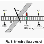
Automatic gate control
It deals with two things. Firstly, it deals with the reduction of time for which the gate is being kept closed. And secondly, to provide safety to the road users by reducing the accidents that usually occur due to carelessness of road users and at times errors made by the gatekeepers.
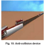
Anti-collision device
ACDs have knowledge fixed intelligence. They take inputs from GPS satellite system for position updates and take decisions for timely auto-application of brakes to prevent dangerous ‘collisions’.
Train accidents
A classification of accidents by their consequences:
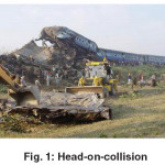
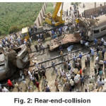
Head-on-collision and Rear-end collision
Head on collision; one type of train accident is when two trains collide front face with each other or train colliding on the same track from opposite ends called head on collision.
Rear end collision; the other kind is when a train collides into the other that is in front of it, called a rear end collision.
Warning signs for railway
Indian Railway provides some signs and signals to avoid railway accidents.
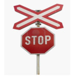
Advance sign
This sign tells you to slow your speed and look and listen for the train, and be ready to stop at the tracks if a train is coming.
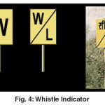
Whistle Indicator
‘W’, or ‘W/L’ on a square yellow board. The ‘W’ is a general whistle indicator while the ‘W/L’ stands for Whistle for Level Crossing. The latter is also seen in Hindi with the characters ‘see/pha’ == ‘seetee bajao – phatak’).
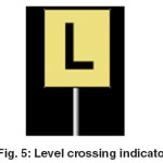
Level Crossing indicator
A black ‘L’ on a square yellow board indicates approach to a level crossing.
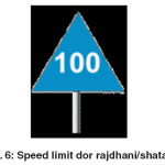
Speed Limit
Rajdhani/Shatabdi: Number on blue board indicates a special speed limit (in km/h) for Rajdhani and Shatabdi trains. Text is in white.
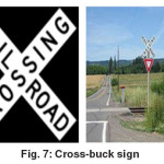
Cross-bucks Sign
Cross bucks are located at all grade crossings on both approaches to the crossing. Form an X via the intersection of two 1200 mm x 200 mm retro-reflective pieces. A cross buck sign provides the last indication to the driver where the crossing is located.
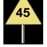
Speed Limit
Number on triangular yellow board speed limit in km/h. ‘KMPH’ or ‘KM/H’ may optionally appear below the number. Black text.
Technology used in model
Gate control
Using simple electronic device, we have tried to control the railway gate. A sensor is placed at certain distance of railway gate to detect the train. When a train comes it detects the train and displayed it on the monitor and then it controls the railway gate and reduces the railway accident.
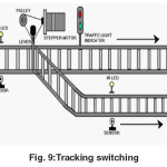
Track switching
Considering a situation where is an express train and a local train are travelling on the same track in opposite directions; the express train is permitted to travel on the same track and the local train has to switch on to the other track. Indicator lights have been provided to avoid collisions. In this, switching operation is performed using a stepper motor. In practical purposes this can be achieved using electromagnets.
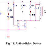
Anti-collision device
Anti-Collision Devices have knowledge fixed intelligence. They take inputs from GPS satellite system for position updates and take decisions for timely auto-application of brakes to prevent dangerous ‘collisions’.
ACDs fitted (both in Locomotive and Guard’s Van of a train) act as a watchdog in the dark as they constantly remain in lookout for other train bound ACDs, within the braking distance required for their relative speeds.
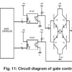
In this project, we use a slow speed gear motor for open and close the railway track when train arrives. Working voltage of these motor are 9 volt to 12-volt dc. We use two power sources in this project. One is used for the motors and second is used for the controller. For controlling a dc motor we use H bridge circuit. We use four transistor circuits to control the movement of dc motor for onward and reverse movement.
Combination of track switching and gate control
We use two platforms to make easy model which can make any number of platform. When train reaches at certain distance from the railway track a set of sensors are placed to detect the train and two pairs of sensor are placed on other side of track to detect the train.
When the train is at the first pair of sensors it sends a signal to microcontroller to know the availability of plat form. Hereafter checking availability microcontroller operates stepper motor to change the track.
Anti-collision device
ACDs fixed (both in Locomotive and Guard’s Van of a train) act as a watchdog in the dark as they continuously remain in lookout for other train bound ACDs, within the braking distance necessary 40for their relative speeds. They communicate through their radios and identify each other. If they happen to find themselves on the same track and coming closer to each other, they automatically restrain and stop each other, thereby preventing dangerous head-on and rear-end collisions.
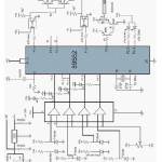
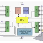
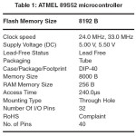
Microcontroller
The AT89S52 is a low-power, high-performance CMOS 8-bit microcontroller with 8Kbytes of in-system programmable Flash memory. The device is manufactured using Atmel’s high-density non-volatile memory technology and is compatible with the industry-standard 80C51 instruction set and pin out. The on-chip flash allows the program memory to be reprogrammed in-system or by a conservative non-volatile memory programmer. The AT89S52 provides the following standard features: 8K bytes of Flash, 256 bytes of RAM, 32 I/O lines, Watchdog timer, two data pointers, three 16-bit timer/counters, a six-vector two-level interrupt architecture, a full duplex serial port, on-chip oscillator, and clock circuitry.
Conclusion
This paper is suitably fulfilled the basic things such as avoidance of accidents inside the gate and the avoidable of a gatekeeper. It avoids the railway accidents and provides safety. We have seen little improvement in railway accidents. We also observed stronger safety records in certain areas and believe they are the result of constant efforts to improve safety. We demonstrate that it is possible to improve the overall safety of the railway system in India. We believe that success depends on both the railway industry and the regulator working together to achieve that common goal. The proposed system provide the means for real time inspection, review and data collection for the purpose of maintenance on the movable and fixed facilities for the guarantee of operation safety and maintenance efficiency as well as the safety appraisal decision-making system based on the share of safety data.
Acknowledgement
We are very thankful to Mr. Vishal Bharti, Head of Department of Computer Science and Engineering who gives us the opportunity to make the research paper and also our research mentor Prof. Sarita, Associate professor of Computer Science And Engineering who has guided us in every step in completing this research paper and also thanking to our project mentor Prof. Neha Malik, Assistant professor of Computer Science And Engineering who has guided in completing our project since now. We are in last phase of our project and till from starting she is helping us to clear out every hurdle.
References
- A complete reference of Micro Controllers, “Natwar Singh”.
- Railways overview- a technical magazine.
- The 8051 microcontroller and embedded systems “Muhammad Ali Mazidi”
- 8051 Microcontroller: An Applications Based Introduction by “David Calcutt, Frederick Cowan, and Hassan Parchizadeh”
- C and the 8051 by Tom Schultz.
- Der Keil C51-Compiler by “Michael Baldischweiler”
- San Francisco s “Advanced automatic warning signal system” in Proc. CERIE 2010, paper C, p. 297, 2010

This work is licensed under a Creative Commons Attribution 4.0 International License.