Introduction
One of the strongest advantages of mobile and wearable computing systems is the ability to support location-aware or location-based computing, offering services and information that are relevant to the user’s current locale3. Location-aware computing systems need to sense or otherwise be told their current position, either absolute within some reference coordinate system or relative to landmarks known to the system.
Augmented reality systems, which overlay spatially registered information on the user’s experience of the real world, offer a potentially powerful user interface for location-aware computing. To register visual or audio virtual information with the user’s environment, an augmented reality system must have an accurate estimate of the user’s position and head orientation.
There are many competing tracking technologies, which vary greatly as to their range, physical characteristics, and how their spatial and temporal accuracy is affected by properties of the environments in which they are used. One particularly appealing approach is to combine multiple tracking technologies to create hybrid trackers, using the different technologies either simultaneously or in alternation, depending upon the current environment. In all cases, however, if information registration techniques designed for accurate tracking are employed when tracker accuracy is too low, virtual information will not be positioned properly, resulting in a misleading or even unusable user interface. To address this problem, we are developing an experimental mobile augmented reality system that adapts its user interface automatically to accommodate changes in tracking accuracy. Our system employs different technologies for tracking a user’s position, resulting in a wide variation in positional accuracy. These technologies include a ceiling-mounted ultrasonic tracker covering a portion of an indoor lab, and a real-time kinematic GPS system covering outdoor areas with adequate visibility of the sky. For areas outside the range of both of these tracking systems, we have developed a dead-reckoning approach that combines a pedometer and orientation tracker with environmental knowledge expressed in spatialmaps and accessibility graphs. Our adaptive user interface is designed to serve as a navigational assistant, helping users to orient themselves in a unfamiliar environment. Inferencing and path planning components use the environmental knowledge to guide users toward targets that they choose. into account when processing and presenting information to the user. While augmented reality systems can be viewed as falling into this category, location based systems become interesting when the supported range of locations expands beyond a single laboratory room. There is a wealth of work regarding such types of applications within the wearable and ubiquitous computing area. Both can make good use of augmented reality to visualize abstract and special information as described in (Starner, Mann, Rhodes, Levine, Healey, Kirsch, Picard & Pentland 1997). To employ AR in a large environment mobile systems were built that support the graphical and computational demands of it. Examples of such developments are the Touring machine by (Feiner, MacIntyre, H¨ollerer & Webster 1997) or the Tinmith system by (Piekarski & Thomas 2001). The Touring machine is also a good example of a location based application.
Literature analysis
Many approaches to position tracking require that the user’s environment be equipped with sensors17, beacons15,20,6, or visual fiducials20. Tethered position and orientation tracking systems have attained high accuracy for up to room-sized areas using magnetic13, ultrasonic, and optical technologies, including dense arrays of ceiling-mounted optical beacons1.
Alternatively, sparsely placed infrared beacons can support tetherless positiononly tracking over an entire building at much lower accuracy18,6.
Mobile phone technology has also been used to provide coarse position tracking over a potentially unlimited area. Among others, British mobile phone companies Vodafone and BT Cellnet already offer cell identification and cell broadcasting services, that of alternate representations for a specific augmentation. We believe that their notion of only one single pose measurement error value needs to be extended to distinguish position errors (as we explore here) from orientation errors, and to account for other varying tracking characteristics (e.g., update rates or likelihood to drift). Butz and colleagues7 describe an adaptive graphics generation system for navigational guidance. While our projects share many of the same goals, we concentrate on user interfaces for augmented reality, while their initial implementation focuses on small portable devices and stationary displays.
Indoor tracking
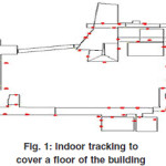
To build an environment where we could test drive our mobile AR kit, we mplemented an indoor tracking solution to cover a floor of our building. As we did not have access to a proprietary buildingwide positioning infrastructure (such as AT&T Cambridge’s BAT system used by (Newman et al. 2001)), we choose to rely on a hybrid optical/ inertial tracking solution. This approach proved very flexible in terms of development of positioning infrastructure, but also pushes the limits of what ARToolkit tracking can provide.
Complementary tracking modes
The experimental adaptive mobile augmented reality user interface that we describe in this paper is intended to assist a user in navigating through an unfamiliar environment. It is designed for use with our custom-built backpack computer, based on an Intel Pentium III 700MHz processor, and nVidia GeForce2MX 3D graphics accelerator, and connected to our campus backbone through IEEE 802.11b wireless networking [18]. The user interface is presented on a Sony LDI-D100B see-through head-worn display, and is implemented in Java 3D. Our system relies on different technologies for tracking a user’s position in three different circumstances: within part of a research laboratory served by a high-precision ceiling tracker, in indoor hallways and rooms outside of the ceiling tracker range, and outdoors. Orientation tracking is done with an InterSense IS300 Pro hybrid inertial/ magnetic tracker. We can track both the user’s head and body orientation by connecting head-mounted and belt-mounted sensors to the unit. When walking around indoors, we have to switch off the magnetic component of the tracker to avoid being affected by stray magnetic fields from nearby labs and rely on purely inertial orientation information. When outdoors with line of sight to at least four GPS or Glonass satellites, our system is position tracked by an Ashtech GG24 Surveyor RTK differential GPS system. For indoor tracking, we use a Point Research PointMan Dead-ReckoningModule (DRM) and an InterSense Mark II SoniDisk wireless ultrasonic beacon. The systemcan detect whether the beacon is in range of an InterSenseMark II ceiling tracker. The Mark II tracker is connected to a stationary tracking server and the position updates of the roaming user’s Soni-Disk beacon are relayed to the user’s wearable computer using our Java-based distributed augmented reality infrastructure18. Tracking accuracies and update rates vary widely among these three position tracking approaches. The IS600 Mark II ceiling tracker can track the position of one SoniDisk to a resolution of about 1 cm at 20–50 Hz. The outdoor RTK differential GPS system has a maximum tracking resolution of 1–2 cm at an update rate of up to 5 Hz. The GPS accuracy may degrade to 10 cm, or even meter-level when fewer than six satellites are visible. If we lose communication to our GPS base station, we fall back to regular GPS accuracy of 10–20m. Our augmented reality user interface for navigational guidance adapts to the levels of positional tracking accuracy associated with different tracking modes. changes. In this paper, we focus on ceiling tracker and DRM tracking modes.
Wide area indoor tracking using dead reckoning
Whenever the user is not in range of an appropriate ceiling tracker,our system has to rely on local sensors and knowledge about the environment to determine its approximate position. Unlike existinghybrid sensing approaches for indoor position tracking [16, 20, 10], we try to minmize the amount of additional sensor information to collect and process. The only additional sensor is a pedometer (the orientation tracker is already part of our mobile augmented reality system). Compared with2 who use digital compass information for their heading information, we have a much more adverse environment to dealwith. Therefore, we decided to rely on inertial orientation tracking and to correct for both the resulting drift and positional errors associated with the pedometerbased approach by means of environmental knowledge in the form of spatial maps and accessibility graphs of our environment. Our dead reckoning approach uses the pedometer information from the DRM to determine when the user takes a step, but uses the orientation information from the more accurate IS300 Pro orientation tracker instead of the DRM’s built-in magnetometer. We do this because the IS300 Pro’s hybrid approach is more accurate and less prone to magnetic distortion. Furthermore, we have the option to use the IS300 Pro in inertial-only tracking mode
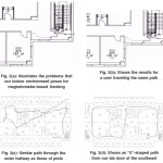 |
Figure 2(a): Illustrates the problems that our indoor environment poses for magnetometer-based tracking, (b): Shows the results for a user traveling the same path, (c): Similar path through the outer hallway as those of plots, d): Shows an “S”-shaped path from our lab door at the southeast
Click here to View figure
|
Figure 2 (b) shows the problems that our indoor environment poses for magnetometer-based tracking. The plot corresponds to a userwalking around the outer hallways of the 6th floor of our research building, using the IS300 Pro tracker in hybrid mode. The plot reflects a lot of magnetic distortion present in our building. In particular, the loop in the path on the left edge of the plot dramatically reflects the location of a magnetic resonance imaging device for material testing two floors above us. For indoor environments with magnetic distortions of such proportions we decided to forgo magnetic tracker information completely and rely on inertial orientation data alone.
Figure 2 (b) shows the results for a user traveling the same path, with orientation tracking done by the IS300 Pro tracker in purely inertial mode. The plot clearly shows much straighter lines for the linear path segments but there is a linear degradation of the orientation information due to drift, resulting in the “spiral” effect in the plot, which should have formed a rectangle.
Figure 2(c) and 2(d) show the results after correcting the method of 2(b) with information about the indoor environment. Plot 2(c) shows a similar path through the outer hallway as those of plots 2(a) and 2(b). In contrast, plot 2(d) shows an “S”-shaped path from our lab door at the southeast, around the outside hallway at the east and north, down through the center corridor to the south hallway, then heading to and up the west hallway, and across the north hallway back to the north end of the center corridor. To perform these corrections, we use two different representations of the building infrastructure in conjunction: spatial maps and accessibility graphs. Spatial maps accurately model the building geometry (walls, doors, passageways), while accessibility graphs give a coarser account of the main paths a user usually follows.Figure compares the two representations for a small portion of our environment. Both the spatial map and the accessibility graph were modeled by tracing over a scanned floorplan of our building using a modeling program that we developed. The spatial map models all walls and other obstacles. Doors are represented as special line segments (as denoted by the dashed lines connecting thedoor posts). For each step registered by the pedometer, and taking into account the heading computed by the orientation tracker, ourdeadreckoning algorithm checks the spatial map to determine if the user will cross an impenetrable boundary (e.g., a wall). If that is the case, then the angle of collision is computed. If this angle is below a threshold (currently 30 degrees), the conflict is classified as an artifact caused by orientation drift and the directional information is corrected to correspond to heading parallel to the obstacle boundary. If the collision angle is greater than the threshold, the system searches for a segment on the accessibility graph that is close to the currently assumed position, is accessible from the currently assumed position (i.e., is not separated from it by an impenetrable boundary, which is checked with the spatial map data structure), and is the closestmatch in directional orientation to the currently assumed heading information. The system assumes that the user is really currently located at the beginning of that segment and changes the last step accordingly to transport the user there. Doors are handled as special cases. First, the sensitive door area is assumed to be larger than the doorframe itself (currently, all walls in the immediate continuation of the door 1 m to either side will trigger door events if the user attempts to cross them). In case of a door event, the angle of collision is determined. If the angle is below our 30 degree threshold, the system behaves as if the door were a simple wall segment and no passage occurs. If the angle is greater than 60 degrees, the system assumes that the user really wanted to enter through that door and proceeds correspondingly. If the angle is in between the two thresholds, the system continues with the accessibility graph search described above. Our initial results with this approach are very promising. The plot in Figure 2(d) for example corresponds to a path along which the user successfully passed through three doors (the lab door at the east end of the south corridor, and two doors at the north end and middle of the center corridor), and never deviated far from the correct position. We are in the process of collecting more quantitative results on the adequacy of our approach.
The adaptive augmented reality user interface
A view through the see-through head-mounted display when the user is accurately position tracked by the ceiling tracker (Figure 2(a) & 2(b)). The system overlays features of the surrounding room, in this case a wireframe model consisting of our lab’s walls and ceiling, doors, static objects of interest (e.g., a rear projection display), and rooms in the immediate neighborhood. Labels are realized as Java 3D [12] Text2D objects: billboarded polygons with transparent textures representing the label text. Labels are anchored at their corresponding 3D world positions, so that closer objects appear to have bigger labels. The color scheme highlights important objects (e.g., results of a navigational query, described in Section 5, and passageways from the current room to the main corridors). When we roam with our mobile system—away from the ceiling tracker, but not yet outdoors where GPS can take over—we currently depend upon our hybrid, dead-reckoning system for positional data. As a result, we have relatively more accurate orientation tracking than position tracking. To leverage the relatively superior orientation accuracy in this situation, we have chosen to situate much of the overlaid material when roaming within the context of a World in Miniature (WIM)30: a scaled-down 3D model Figure 3(b) Augmented reality user interface in accurate tracking mode (imaged through see-through head-worn display). Labels and features (a wireframe lab model) are registered with the physical environment. of our environment. Our WIM has a stable position relative to the user’s body, but is oriented relative to the surrounding physical world. That is, it hovers in front of the user, moving with her as she walks and turns about, while at the same time maintaining the same 3D orientation as the surrounding environment of which it is a model. In related work on navigational interfaces, Darken and colleagues11 explore different ways of presenting 2D and 3D map information to a user navigating in a virtual environment. They conclude that while there is no overall best scheme for map orientation, a selforienting “forward-up” map is preferable to a static “north-up” map for targeted searches. The WIM is a 3D extension of the “forward up” 2D option in Darken’s work. Because our WIM’s position is body-stabilized, the user can choose whether or not to look at it is not a constant consumer of head-stabilized head-worn display space, and doesn’t require the attention of a tracked hand or arm to position it. If desired, the WIM can exceed the bounds of the HMD’s restricted field of view, allowing the user to review it by looking around, since the head and body orientation are independently tracked. The WIM incorporates a model of the environment and an avatar representation of the user’s position and orientation in that environment. It also provides the context in which paths are displayed in response to user queries about routes to locations of interest. When the user moves out of range of the ceiling tracker, position tracking is shifted to the dead-reckoning tracker. To notify the user that this is happening, we first replace the registered world overlay with the WIM model, but at full-scale and properly registered. Then theWIM is interpolated in scale and position to its destination configuration15. Figure 3(a) shows the user interface just after this transition. Because the head–body alignment is relatively constant between these two pictures, the position of the projected WIM relative to the display is similar in both pictures, but the differing position and orientation of the body relative to the world reveal that theWIM is world aligned in orientation. These images also include route arrows that point the way along a world-scale path to a location that the user has requested (in this case, the nearest stairway). As the user traverses this suggested path, the arrows advance, always showing the two next segments. TheWIM also displays the entire path, which is difficult to see in these figures because of problems imaging through the see-through head-worn display. (A more legible view of a path is in shown in Figure , which is a direct frame-buffer capture, and therefore doesn’t show the real world on which the graphics are overlaid.)
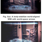 |
Figure 3(a): A body-stabilize world-aligned WIM with world-space arrows (b): The same WIM with the user at a different position and orientation
Click here to View figure
|
Limitations and future enhancements
Augmented reality still has some challenges to overcome. For example, GPS is only accurate to within 30 feet (9 meters) and doesn’t work as well indoors, although improved image recognition technology may be able to help. AR faces technical challenges regarding for example binocular (stereo) view, high resolution, colour depth, luminance, contrast, field of view, and focus depth. However, before AR becomes accepted as part of user s everyday life, just like mobile phones and personal digital assistants(PDAs), issues regarding intuitive interfaces, costs, weight, power usage, ergonomics, and appearance must also be addressed. A number of limitations, some of which have been mentioned earlier, are categorized here.
Portability and outdoor use
Most mobile AR systems mentioned in this survey are cumbersome, requiring a heavy backpack to carry the PC, sensors, display, batteries, and everything else. Connections between all the devices must be able to withstand outdoor use, including weather and shock, but universal serial bus (USB) connectors are known to fail easily. However, recent developments in mobile technology like cell phones and PDAs are bridging the gap towards mobile AR. Optical and video see-through displays are usually unsuited for outdoor use due to low brightness, contrast, resolution, and field of view. However, recently developed at Micro Vision, laser-powered displays offer a new dimension in head-mounted and hand-held displays that overcomes this problem. Most portable computers have only one CPU which limits the amount of visual and hybrid tracking. More generally, consumer operating systems are not suited for real-time computing, while specialized real-time operating systems don t have the drivers to support the sensors and graphics in modern hardware.
Depth perception
One difficult registration problem is accurate depth perception. Stereoscopic displays help, but additional problems including accommodation-vergence conflicts or low resolution and dim displays cause object to appear further away than they should be [2]. Correct occlusion ameliorates some depth problems13, as does consistent registration for different eyepoint locations [8]. In early video see-through systems with a parallax, users need to adapt to vertical displaced viewpoints. In an experiment by Biocca and Rolland [5], subjects exhibit a large overshoot in a depth-pointing task after removing the HMD.
Overload and over-reliance
Aside from technical challenges, the user interface must also follow some guidelines as not to overload the user with information while also preventing the user to overly rely on the AR system such that important cues from the environment are missed [6]. At BMW, Bengler and Passaro [9] useguidelines for AR system design in cars, including orientation on the driving task, no moving or obstructing imagery, add only information that improves driving performance, avoid side effects like tunnel vision and cognitive capture and only use information that does not distract.
Inference
Thus we have seen that augmented reality is a combination of a real scene viewed by a user & a virtual scene generated by computer that auguments the scene with additional information. It is actually created to identify the systems which are mostly synthetic with some real world imagery added such as texture mapping video onto virtual objects. This is a distinction that will fade as the technology improves and the virtual element in the scene becomes less distinguishable from the real ones.
Conclusion
We have described a mobile augmented reality system that employs different modes of tracking a user’s position, resulting in a wide variation in positional accuracy between the different modes. One of these tracking modes is established by a new dead-reckoning tracking module that makes use of pedometer and orientation information, and applies corrections derived from knowledge about the user’s immediate environment in the form of area maps and accessibility graphs. We presented the early stages of an augmented reality user interface that automatically adapts to the changes in tracking accuracy associated with these different tracking modes, and modifies its visual representation accordingly. Finally we introduced the knowledge-based components used in our augmented reality user interface for navigational guidance. Our research to date raises several interesting questions. Does a 3D WIM, stabilized in some manner with respect to the user, inviting a sense of “forward,” offer measurable navigational advantages over a 2D map with an implicit sense of “up” that might be screen-stabilized? Is a body-stabilized, world-oriented WIM significantly more powerful than ones that are head-stabilized and world aligned, head-stabilized and north-forward, or body-stabilized and north-forward? These questions suggest the need for taxonomy of navigational “maps.” Possible principal dimensions for such a taxonomy are spatial dimensionality (2D or 3D), positional stabilization, and orientational alignment. A number of issues could be addressed through user studies. Considering head-stabilization of WIM position, might it be better to fix the height, allowing the head to look up (away from) and down (to) the WIM, or should the WIM remain within the frustum regardless of where the head looks? Given body tabilization and world-orientation, might it be better to have the user immersed in the WIM with the centroid of her world-sized, physical body coincident with her position in the WIM? Or, as we conjecture in the design of our system, might it be better to situate the WIM with its centroid (and its entire volume) somewhat in front of the user’s body? Immersing the user directly in a WIM would avoid the indirection and potential distraction implicit in representing her in the WIM by an avatar, but does this offset the presumed disadvantage of having the user’s physical body displace considerably more than its realistic “share” of the WIM’s volume? Does one really want the user to have to look “inside” herself to see the miniature version of the floor several meters in front of where she currently stands? Can she tell exactly where she is in the miniature, without some virtual representation of herself? Should the user’s locus in the WIM be body-stabilized (rather than stabilizing the WIM’s centroid), and the user’s position be represented by a virtual belt-buckle that would overlay the real thing.
References
- 3rdTech. http://www.3rdtech.com/HiBall.htm, (2001).
- H. Aoki, B. Schiele, and A. Pentland. Realtime personal positioning system for wearable computers. In Proc. ISWC ’99 (Third Int. Symp. on Wearable Computers), pages 37– 43, San Francisco, CA, (1999).
- H. Beadle, B. Harper, G. Maguire Jr., and J. Judge. Location aware mobile computing. In Proc. ICT ’97 (IEEE/IEE Int. Conf. on Telecomm.), Melbourne, Australia (1997).
- R. Behringer. Registration for outdoor augmented reality applications using computer vision techniques and hybrid sensors. In Proc. IEEE Virtual Reality ’99: 244–251 (1999).
- J. Borenstein, H. Everett, and L. Feng. Navigating Mobile Robots: Systems and Techniques. A K Peters, Natick, MA (1996).
- A. Butz, J. Baus, and A. Kr¨uger. Augmenting buildings with infrared information. In Proceedings of the International Symposium on Augmented Reality ISAR 2000, pages 93–96. IEEE Computer Society Press, (2000).
- A. Butz, J. Baus, A. Kr¨uger, and M. Lohse. A hybrid indoor navigation system. In IUI2001: International Conference on Intelligent User Interfaces, New York, 2001. ACM.
- Cambridge Position Systems. Cursor E-OTD mobile location technology. http:// www.cursor-system.com/ sitefiles/ cursor/ tech technology.htm, 2001.
- Cell broadcasting technology. http://www.btcellnet.net/, http:// www.vodaphone.uk.co, (2001).
- B. Clarkson, K. Mase, and A. Pentland. Recognizing user context via wearable sensors. In Proc. ISWC ’00 (Fourth Int. Symp. on Wearable Computers), pages 69–75, Atlanta, GA, October 16–17 2000.
- R. Darken and H. Cevik. Map usage in virtual environments: Orientation issues. In Proceedings of IEEE VR ’99: 133-140 (1999).
- M. Deering and H. Sowizral. Java3D Specification, Version1.0.SunMicrosystems, 2550 Garcia Avenue,Mountain View, CA 94043, USA, Aug. (1997).
- E. Dijkstra. A note on two problems in connexion with graphs. Numerische Mathematik, 1: 269-271 (1959).
- F. M. Donini, M. Lenzerini, D. Nardi, and A. Schaerf. Reasoning in description logics. In G. Brewka, editor, Principles of Knowledge Representation, Studies in Logic, Language and Information, pages 193–238. CSLI Publications (1996).
- I. Getting. The global positioning system. IEEE Spectrum, 30(12): 36-47 (1993).
- A. R. Golding and N. Lesh. Indoor navigation using a diverse set of cheap, wearable sensors. In Proc. ISWC ’99 (Third Int. Symp. on Wearable Computers), pages 29–36, San Francisco, CA, (1999).
- A. Harter, A. Hopper, P. Steggles, A. Ward, and P. Webster. The anatomy of a context-aware application. In Proc. of the Fifth ACM/ IEEE Int. Conf. on Mobile Computing and Networking(MobiCom), pages 59–68, Seattle, WA, Aug. 1999.
- T. H¨ollerer, S. Feiner, T. Terauchi, G. Rashid, and D. Hallaway.ExploringMARS: Developing indoor and outdoor userinterfaces to a mobile augmented reality system. Computers and Graphics,23(6): 779-785 (1999).
- InterSense IS-900 Wide Area Precision Motion Tracker. http://www.isense.com, (2001).
- H. Kato, M. Billinghurst, I. Poupyrev, K. Imamoto, and K. Tachibana. Virtual object manipulation on a table-top ar environment. In Proceedings of the International Symposium on Augmented Reality ISAR 2000, pages 111–19. IEEE Computer Society Press, (2000).

This work is licensed under a Creative Commons Attribution 4.0 International License.