Introduction
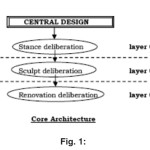
The evaluation scheme of model driven architecture should be considered as an all-round effort instead of concentrated. It must target the entire major and minor steps before having the layout of such scheme. The targeted evaluation scheme must be composed of three-layer architecture:
The above core architecture reflects the three major layers in the evaluation scheme. However it excludes all the major and minor considerations. The forthcoming headings will precede the details of each layer and conclusion will shape the root scheme finally.
Layer 01 (Stance Deliberation)
The layer o1 instances are considered on the basic of POINTS followed by GRADES. Let us consider first the instances of the layer before mentioning the points and Grades. We have the following instance to be considered,
´ Either the milieu of a system. (A-e)
´ Either operation of the system. (A-o)
´ Either use of platform by a system. (A-p)
´ All of the three. (A-t)
With the Grades follows them.
Each grade has a point range from 0 – 9. average point Grade lower to a range of 6.5 reveals that the instance needs modification or to be reconsidered (it must ne noted that designer or analyst should consider the purpose, need or interest of a user or community before selecting the instances) Each instance can be marked on the following points…
- obligation specification report.
- Analysis of system especially with respect to either of the grades i.e. milieu, operation and platform feasibility.
- Independency in design specifications with respect to either or all of the instances.
- Selection of front and backend with respect to either or all of the instances.
- Implementation report prospective.
Example 01
Consider if the target/considered instance is A-p, and the grade points are as follows.. 8.2, 7.8, 6.9, 5.4, 8.0 and the average grade point are 8.2 + 7.8 + 6.9 + 5.4 + 8.0 = 7.26. now the instance can be picked of from the layer o1.
It could be written as A-e 7.26; A-e 7.26; A-p 7.26; A-t 7.26. With this the layer o1 considerations are come to an end.
Layer 02 (Sculpt Deliberation)
Model consideration is the next significant task in the core architecture of central design. Sculpt consideration is directly proportional to the requirement of the system to be developed. Depending on the same we can categorized them as follows:
a) Computational liberated
b) Platform precise
c) Platform liberated.
Consider the evaluation scheme as to judge the above mentioned criteria.
´ For first two grade points from 0-9 should be awarded with respect to the degree. Again any degree up to or above 7.5 is to be considered.
´ Cost factor is considered on the following remark “till scale of benefit is greater than the cost” till then cost is ok. When “scale of benefit is equal or less than the cost “then cost factor should not be considered.
´ As far as security is considered since it cannot be updated to a definite level of satisfaction so it must be up to the mark with respect to the minimal. However it should get checked from time to time and updated too.
´ Integrity of a system is another area to be concerned. A well integrated environment leads to smooth working conditions. So analysis of intact must be done in a proper manner and any degree up to 7.5 or above is suited well to a system.
(DEGREE is considered up to 7.5 only as there is always a room for improvement so no one can have perfect 10 remarks)
Evaluation of Platform precise Model
Evaluation of Computational Liberated Model
The Computational Liberated model when considered indicates the computing time, methods, techniques that are to be considered least and rest specifications like platform, standards are to be taken in a significant manner.
Therefore any framework for evaluation of its performance must revolve around it. It is assumed that the primary user of the CIM is domain practitioner, and is not having knowledge about the models or artifacts that are used to realize the functionality for which the requirements are articulated in the CIM. So any model design with respect to CIM must be environment centric. Emphasis on environment of a system must be based on following criteria:
- Degree of user friendliness.
- Degree of Robust.
- Level of Secured environment
- Cost factor
- Degree of Intact
The platform precise model as name suggests stress on platform of a system leaving other things behind. A platform precise model provides a set of technological concepts, representing the dissimilar kinds of parts that build up a stage and the services provided by that platform. It also provides, for use in a platform exact replica, concepts representing the dissimilar kinds of elements to be used in specifying the use of the platform by an application.
In the case of Platform precise Model it must be noticed that it has combo features of platform liberated and itself. It however stress on the use of specific platform by the system. Considerations must be on the following niceties:
- Degree of dependency it holds for platform.
- Degree of Mobility with the platform.
- Degree of flexibility with other platforms.
- Measure of enhancement level on same platform
- Security and reliability on same platform
- Status level of system on a platform with respect to the global arena.
(The above factors are concluded by studying software factories approach on system development: Reference: Greenfield, Jack and Short, Keith: Software Factories. Wiley Publishing,2004. ISBN 0-471-20284-3) The degrees must again be either or greater than 7.5 par out of 10 as to be considered. Measurement of enhancement level is performed on two parameters:
(a) Requirement judged by proper requirement analysis.
(b) Competing with global pace.
(C) Evaluation of Platform liberated model
A platform liberated model is a sight of a system from the platform independent stance. A PLM exhibits a particular extent of platform sovereignty so as to be appropriate for apply with a number of unlike platforms of related type. Development of virtual system is the most common technique. In the case of virtual machine, it can be realized as a platform itself. Basically it is a combination of parts and services that can be provided to any other platform. Designing the Evaluation of such platform is most difficult one as it required accuracy in the same way as this model could be served to any other platform. All an all it describe the system, which can be associated on every platform. In this context some benchmarks must be considered as to ensure a class evaluation scheme.
- Services offered (Direct & Indirect both)
- Degree of flexibility
- Degree of compatibility
In the above mentioned scenario degree of flexibility realizes its importance when platform transformation is required. Compatibility comes to us when other platform tries to engulf the behavior of present platform along with its own features.
The degrees must again be either or greater than 7.5 par out of 10 as to be considered. Measurement of compatibility level is the most fluctuate scenario and may vary with different models. (Degree assigned to each content is the matter of ANALYSIS phase and is proportional to analyst viewpoint).
Layer 03 (Renovation Deliberation)
The subsequent walk is to take the noticeable PIM and convert it into a PSM. This can be finished manually, with computer aid, or automatically. Model transformation is the process of converting one model to another model of the same system. The input to the alteration is the marked PIM and the mapping. The result is the PSM and the record of transformation.
There is a variety of tools sustain for sculpt transformation. Transformations can employ different mixtures of guidebook and usual tranyeta sformation. There are different approaches to put into a replica the information obligatory for a transformation from PIM to PSM. Four different transformation approaches described here demonstrate the assortment of possibilities:
- Manual transformation
- Transforming a PIM that is prepared using a profile.
- Transformation using patterns and markings.
- Automatic transformation.
Manual Transformation
In order to make the transformation from PIM to PSM, design decisions must be made. These design decisions can be made during the course of developing a design that conforms to engineering necessities on the accomplishment. This is a useful loom, because these decisions are considered and taken in the context of a specific implementation design. This manual transformation procedure is not really different from how much superior software design work has been through for years. The MDA approach adds value in two Ways:
´ The explicit peculiarity between a platform independent model and the changed platform specific model,
´ The verification of the transformation.
Transforming a PIM Prepared Using a Profile
A PIM may be prepared using a platform independent UML profile. This model may be transformed into a PSM expressed using a second, platform specific UML profile.
The transformation may involve marking the PIM using marks provided with theplatform specific profile. The UML 2 profile extension mechanism may include the specification of operations; then transformation rules may be specified using operations, enabling the specification of a transformation by a UML profile.
Transformation Using Patterns and Markings
Patterns may be used in the specification of a mapping. The mapping includes a pattern and marks corresponding to some elements of that pattern.
In model instance transformations the specified marks are then used to prepare a marked PIM. The marked elements of the PIM are transformed according to the pattern to produce the PSM.
Example
A decorator pattern with two roles, decoration and decorated supplies a mark, decorated. When this mark is applied to a class in a model, the transformation might produce a class corresponding to that class, with additional operations and attributes, a new class, corresponding to the decoration, and an association between those classes.
Several patterns may be combined to produce a new pattern. New marks can then be specified for use with the new pattern. In model type transformations, rules will specify that all elements in the PIM which match a particular pattern will be transformed into instances of another pattern in the PSM. The marks will be used to bind values in the matched part of the PIM to the appropriate slots in the generated PSM. In this usage the target patterns can be thought of as templates for generating the PSM, and the use of marks as a way of binding the template parameters.
Automatic Transformation
There are contexts in which a PIM can provide all the information needed for implementation, and there is no need to add marks or use data from additional profiles, in order to be able to generate code. One such is that of mature component-based development, where middleware provides a full set of services, and where the necessary architectural decisions are made once for a number of projects, all building similar systems (for example, there is a component based product line architecture in place). These decisions are implemented in tools, development processes, templates, program libraries, and code generators.
In such a context, it is possible for an application developer to build a PIM that is complete as to classification, structure, invariants, and pre-and postconditions. The developer can then specify the required behavior directly in the model, using an action language. This makes the PIM computationally complete; that is, the PIM contains all the information necessary to produce computer program code. In this context, the developer need never see a PSM, nor is it necessary to add additional information to the PIM, other than that already available to the transformation tool. The tool interprets the model directly or transforms the model directly to program code.
Such a PIM, in a mature component development shop, with an established architectural style and with platform specific engineering decisions already made and being reused, can be used to generate code (i.e. components in their code form) not only to different CORBA Components or J2EE platforms, but also to some of the other application server platforms. This assumes that someone has prepared for re-use:
(a) A model of the architectural style
(b) Detail within that model, such as a PIM type system, that can be automatically mapped to the various target platforms
(c) The necessary tool support to deliver the model to the developers in the form of profiles, model conformance checks, links to an IDE, supporting processes, and so forth
(d) A mapping for each target platform.
The point is that, with such development environment support, for a given application, the application developer need develop only a PIM, and code can be directly generated from that PIM. The information that would otherwise be in a visible PSM is effectively pre-packaged, and provided to the application developer within the development environment. Of course, a PSM representing the generated code might be provided for the use of the developer.
Conclusion
The evaluation scheme is basically come up to on three grounds mentioned 1.0. The various categories and sub categories proposed under them are also playing vital role in the evaluation scheme.
The examples, stress points, grading system are thus prepared to evaluate the architecture well and thoroughly. In the case of layer three only procedure is given as it solely depends on nature of transformation and choice of user.
References
- Fred Waskiewicz, The OMG Hitchhiker’s Guide (A Handbook for the OMG Technology (Adoption Process).
- Daniels, Modeling with a Sense of Purpose, IEEE Software,19: (2002).
- Shaw and Garlan, Software Architecture, Prentice Hall ISBN 0-13-182957-2.
- IEEE Recommended Practice for Architectural Description of Software-Intensive Systems IEEE Standard 1471 2000.
- S.W. Ambler, “Agile Model Driven Development Is Good Enough,” IEEE Software,20(5): 71-73 (2003)
- A. Uhl, “Model Driven Architecture Is Ready for Prime Time,” IEEE Software, 20(5): 70, 72 (2003).
- B. Selic, “The Pragmatics of Model-Driven Development,” IEEE Software, 20(5): 19-25 (2003).

This work is licensed under a Creative Commons Attribution 4.0 International License.