Wasim Ahmad Bhat and S.M.K. Quadri
Department of Computer Sciences, University of Kashmir, Srinagar (India).
Article Publishing History
Article Received on :
Article Accepted on :
Article Published :
Article Metrics
ABSTRACT:
FAT file system is the most primitive, compatible and simple file system which still sustains in this era on digital devices, such as mini MP3 players, smart phones, and digital cameras. This file system is supported by almost all operating systems because of its simplicity and legacy. This paper presents review of the basic design technique, constraints and formulas of the most important and building block data structure of FAT32 file system; the FAT data structure.
KEYWORDS:
FAT; File Allocation Table; FAT32; File System; Cluster; Sector
Copy the following to cite this article:
Bhat W. A, Quadri S. M. K. Review of FAT Data Structure of FAT32 File System. Orient. J. Comp. Sci. and Technol;3(1)
|
Copy the following to cite this URL:
Bhat W. A, Quadri S. M. K. Review of FAT Data Structure of FAT32 File System. Orient. J. Comp. Sci. and Technol;3(1). Available from: http://www.computerscijournal.org/?p=2239
|
Introduction
The FAT (File Allocation Table) file system was developed in the late 1970s and early 1980s and was the file system supported by the Microsoft® MS-DOS® operating system.1 It was the primary file system for various operating systems including DR-DOS, FreeDOS, MS-DOS, OS/2 (v1.1) and Microsoft Windows (upto Windows Me). FAT was originally developed for floppy disk drives less than 500K in size. As storage capacity increased, FAT was enhanced to support large storage media. As such we have three fully documented FAT file system types: FAT12, FAT16 and FAT32. exFAT2 is the recent compilation of Microsoft® while KFAT,3 TFAT4 and FATTY5 are the reliability enhancements to the actual design by the same and other researchers.
Certain standards, ECMA-1076 and ISO/ IEC 9293,7,8 for FAT design have been made which include only FAT12 and FAT16 without long filename support.
As compared to other file systems, the performance of FAT is poor as it uses simple data structures, making file operations time-consuming and inefficient disk space utilization in situations where many small files are present. But for same simple design and legacy it is supported by almost all existing operating systems for personal computers. This makes it a useful format for solid-state memory cards and a convenient way to share data between operating systems.
In today’s world, several portable digital devices, such as mini MP3 players, smart phones, and digital cameras are becoming part of our life. These devices exchange data frequently with desktop computers. The PC discovers these devices as standard USB mass storage devices, and automatically mounts the file system volumes inside them. This is possible only if the file system used in the device is supported by the PC’s operating system. This is why the conventional FAT321 file system which can address large storage media and is supported by all major desktop operating systems, is still the most widely used file system in portable digital devices.
Data Structure Ordering of FAT32 Volume
The following table shows the order of the data structures that compose a FAT32 disk volume.
|
Boot Sector
|
Reserved Sector
|
FAT (Copy 1)
|
FAT (Copy 2)
|
File & Directory Sectors
|
A FAT32 file system is composed of four different sections:
- The Boot Sector is located at the beginning of the volume i.e. 0th sector. It includes an area called BPB (BIOS Parameter Block) that begins at offset 11 and contains some basic file system information. The rest of the sector usually contains the boot loader code.
- The Reserved sectors immediately follow Boot Sector. The number of reserved sectors for the volume including the Boot Sector is indicated by BPB at offset 14 of Boot Sector. Typically, the reserved sectors include a File System Information Sector at Sector 1 and a Backup Boot Sector at Sector 6 of the volume.
- The File Allocation Table is an array of 32-bit wide entries and spans over a number of sectors indicated by BPB at offset 36 of Boot Sector. FAT32 has generally two copies of FAT data structure for the sake of redundancy checking disk media while one in case of FLASH media. Bit 7 of the BPB offset 40 of Boot Sector indicates whether the FAT is mirrored or not. This region gives the name FAT to the file system and the suffix 32.
- The File and Directory sectors make up rest of the file system up to the end of volume where the actual file and directory data is stored. FAT32 typically hoses the Root Directory in the first cluster (A cluster is a fixed number of contiguous sectors, the number is indicated by BPB at offset 13 of Boot Sector for the volume) of File & Directory Sectors and is indicated by the BPB at offset 44 of Boot sector.
3. FAT Data Structure of FAT32 File System Volume
All of the FAT file systems were originally developed for the IBM PC machine architecture, thus FAT uses little endian format for entries in the BPB, FATs and File and Directory entries [1]. FAT data structure is a table which stores the information about which clusters are used, free or possibly unusable. In addition to that it stores information about the chain of clusters that belong to a particular file. Depending on the type of FAT file system being used and the size of the volume, cluster sizes vary and number of contiguous sectors per cluster may be 1,2,4,8,16,32 or 64 [1]. As memory cost per capacity is dramatically decreasing every year [9], the maximum number of clusters have dramatically increased, and so the number of bits used to identify each cluster has grown. Thus successive major versions of the FAT format are named after the number of table element bits used to address a cluster: 12, 16, 32 and 64 [2]. In FAT32, FAT entry is 32 bit wide but only lower 28 bits are used to address 2^28 clusters. As such FAT32 volume can be as large as ((2^28) * 64)/2 KB which equals to 8 TB.
3.1. Basic Design Technique
Every file and directory (except Root Directory) on FAT32 volume has an entry in its parent directory containing name, attributes, size, etc. along with the 32-bit wide first cluster number allocated to it. Corresponding to any cluster number, FAT entry can have certain permissible values given below:
|
FAT32 Cluster Entry Values
|
Description
|
|
0x00000000
|
Is Free Cluster
|
|
0x00000001
|
Reserved value
|
|
0x00000002–0x0FFFFFEF
|
Is Used Cluster and value points to next cluster in the chain allocated to file/directory
|
|
0x0FFFFFF0–0x0FFFFFF6
|
Reserved values
|
|
0x0FFFFFF7
|
Some Bad sector in Cluster, Unusable
|
|
0x0FFFFFF8–0x0FFFFFFF
|
Is Last Cluster in file/directory or EOC (End Of Cluster chain) marker
|
Each file/directory may occupy one or more clusters depending on its size and number of sectors per cluster. Thus, a file is represented by a chain of these clusters. However these clusters are not necessarily stored adjacent to one another on the disk’s surface but are often instead fragmented throughout the file & directory sectors.
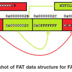
Let’s suppose two files, say MYFILE1.TXT and MYFILE2.TXT are currently residing on a FAT32 volume such that the former is fragmented and 3 clusters long while the later is not fragmented and two clusters long as shown in figure 1.
MYFILE1.TXT has first cluster allocated 0x00000029, FAT contents against that cluster shows another cluster 0x0000002A, then 0x0000002D whose FAT contents show that this cluster is the last cluster in chain. Similarly, for MYFILE2.TXT the first cluster allocated is 0x0000002B whose FAT contents point to next cluster in chain, 0x00000002C, which is the last cluster in chain as pointed by its FAT content.
Constraints
A FAT32 FAT entry actually uses low 28-bits to address clusters. The high 4 bits of a FAT32 FAT entry are reserved and are only changed when the volume is formatted, at which time the whole 32-bit FAT entry should be zeroed, including the high 4 bits. This means all of these 32-bit cluster entry values: 0xA0000000, 0xB0000000, and 0x00000000 indicate a free cluster as the low 28 bits are set to 0.
Suppose a 32-bit free cluster value is currently 0xA0000000 and we want to mark this cluster as bad by storing the value 0x0FFFFFF7 in it. Then the 32-bit entry should contain the value 0xAFFFFFF7, because we must preserve the high 4 bits when we write in the 0x0FFFFFF7 bad cluster mark.
Because the number of bytes per sector as indicated by BPB at offset 11 of Boot sector is always divisible by 4, a FAT32 FAT entry never spans over a sector boundary.
The first two entries in FAT store special values:
The first entry contains a copy of BPB at offset 21 of Boot Sector which is 8 bit long which indicates the type of storage media. The remaining 20 bits between high 4 and low 8 of this entry are set to 1.
The second entry stores the EOC marker. The high order two bits of this entry are sometimes, used for dirty volume management: high order bit if set to 1 indicates that last shutdown was clean otherwise abnormal. The next highest bit if set to 1 indicates that during the previous mount no disk I/O errors were detected10 else there were.
Because the first two FAT entries store special values, there is no cluster 0 or 1. The first addressable cluster in FAT32 FAT data structure is cluster 2, which is the reason why BPB value at offset 44 of Boot Sector which indicates the Root Directory cluster number can not be less than 2 and is usually 2, i.e., the Root Directory is at the start of file/directory region.
3.3. Formulas
All the sector numbers computed here are relative to the first sector of the FAT32 volume, the Boot sector and does not necessarily map directly onto the drive, because sector 0 of the volume is not necessarily sector 0 of the drive due to partitioning and the code snippets are in C-Programming language.
The start of the file/directory region, the first sector of cluster 2, is computed as follows:
FirstDataSector = BPB_ResvdSecCnt + (BPB_NumFATs * FATSz);
BPB_ResvdSecCnt is the number of reserved sectors at offset 14 of Boot sector
BPB_NumFATs is the count of FAT data structures at offset 16 of Boot Sector
FATSz is the count of sectors occupied by one FAT copy at offset 36 of Boot Sector
Given any valid data cluster number N, the sector number of the first sector of that cluster is computed as follows:
FirstSectorofCluster = ((N – 2) * BPB_SecPerClus) + FirstDataSector; BPB_SecPerClus is the count of sectors per cluster at offset 13 of Boot Sector
Given any valid data cluster number N, the FAT sector number which contains its entry and the offset in that FAT sector is computed as follows:
FATOffset = N * 4;
ThisFATSecNum = BPB_ResvdSecCnt +
(FATOffset / BPB_BytsPerSec);
ThisFATEntOffset = FATOffset %
BPB_BytsPerSec;
BPB_BytsPerSec is the count of bytes per sector at offset 11 of Boot Sector
The FAT sector calculated above belongs to first copy of FAT; in case the second copy is to be used the FAT sector is computed as follows:
This FAT Sec Num = BPB_Resvd Sec Cnt + (FAT Off set / BPB_Byts Per Sec)+ FAT Sz;
Conclusion and Future Work
In this paper we discussed the basic & simple design technique for FAT data structure in FAT32 and reviewed the constraints and formulas necessary to handle the FAT32 FAT data structure. Due to its simplicity in design it is widely supported by small digital devices to desktop operating systems. Several things have been left like reliability issues and compatibility problems of FAT data structure, optimized algorithms, etc.
References
- Microsoft Corporation, “FAT32 File System Specification”, http://microsoft.com/whdc/ system/platform/firmware/fatgen.mspx, 2000
- Microsoft Corporation, “Extended FAT File System”, http://msdn2.microsoft.com/en-us/ library/aa914353.aspx, 2007
- M. S. Kwon, S. H. Bae, S. S. Jung, D. Y. Seo, and C. K. Kim, “KFAT: Log-based Transactional FAT File system for Embedded Mobile Systems”, In Proceedings of 2005 US-Korea Conference, ZCTS-142, 2005
- Microsoft Corporation, “Transaction-Safe FAT File System”, http://msdn2.microsoft.c0m/ en-us/library/aa911939.aspx, 2007
- Liang Alei, Liu Kejia, Li Xiaoyong , “FATTY : A reliable FAT File System”, Proceedings of the 10th Euromicro Conference on Digital System Design Architectures, Methods and Tools, Pages: 390-395, 2007.
- Standards – Ecma-107
- Standards – ISO 9293:1987
- Standards – ISO/IEC 9293:1994
- Michael D. Dahlin, “The Impact of Trends in Technology on File System Design” University of California, Berkeley, January 23, 1996.
- Andries E. Brouwer, The FAT file system”, 2002-09-20 http://www.win.tue.nl/~aeb/linux/ fs/fat/fat-1.html
- “Microsoft MS-DOS Programmer’s Reference: version 5.0.”, Microsoft press. 1991.

This work is licensed under a Creative Commons Attribution 4.0 International License.