Introduction
Modeling softwares like I-DEAS, PRO-E, CATIA etc, are an integrated package of mechanical engineering, mainly used in the CAD/CAM application. These softwares were designed to facilitate a concurrent engineering approach to mechanical engineering product design, 3D modeling, analysis and manufacturing applications. The 3D models generated using these softwares contains huge details thereby leading to a heavy file size including description for feature details, history/hierarchy details, physical property data, constraint data, topological data, metadata etc. The file containing these data which are not required for visualization, manipulating such files solely for visualizing in stereo mode results in slow operations. Hence the visualization software came into existence. Visualization is a tool both for interpreting image data fed into computer and for generating images from complex datasets.
Most of the CAD systems are capable to export designed models into STL, VRML files. These
are the file format used to describe shape of the 3D object. The parser program reads scene description described in inputted STL or VRML file. Display module renders the 3D scene with an inclusion of properties applying various lights, material colors, options for solid, wire frame, points and lines viewing, texture mapping, transformation, different camera views etc. The primary objective of this implementation is to provide a fully functional stereo vision system that allows them to explore datasets with less expensive resources during development.
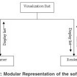
The block diagram figure 1, explains the process carried out in this work. The .stl or .wrl file, which contains description about the object, is given as an input to the program. Parser code stores these details in data structures. Information contained in data structure displayed as object on the screen using OpenGL commands.
Background
The parsing and rendering explained in this paper used for virtual reality visualization system
development. Virtual reality implies an immersive 3D experience. The realm of CAD can be extended to virtual reality by facilitating three-dimensional visualization for virtual evaluation.1 It is a technology that allows user to enter and interact in a world that is generated by computer. This technology is characterized by two essential features:8
It gives 3D real time representation of a real or abstract space. This space is called virtual or artificial environments or spaces.
In more advanced VR system, the virtual world generated by the computer reacts to the actions of the user.
Virtual reality is proposed as a tool to help designers and manufacturing engineers to identify the problem before building the real part.3 Initially an object is designed on a CAD system and formatted in to STL or VRML format. This can be directly translated and displayed in virtual environment. The ability to visualize this prototype, examining it from different angle and eventually manipulating it, offers significant benefit to the designer. This technique will reduce the time required for verification of the model before building them.5
Stereoscopic display is a fundamental part of virtual reality. It is an effective way to enhance insight in 3D scientific visualization.16 This visualization suit demonstrates how a low end, inexpensive viewing technique can be used as a trick to produce the same effect as high-end stereo viewing. This entire visualization suit is divided into Parser and Renderer modules as shown in the figure 2.
Stereo Lithography (STL) Files
The .stl or Stereo Lithography format is an ASCII or binary file designed in modeling. 14 It is a list of triangular surfaces that describe a computer generated solid model. This is the standard input for rapid prototyping. Initially 3D models are designed using modeling software. Most of the modeling software allows export of STL files. There are two storage formats available for STL are ASCII and Binary. ASCII file is a human readable and can be modified if required. Binary versions of STL are more compact. STL file contains a description of the object’s surface in terms of triangles.1 Each individual triangle description defines a single normal vector directed away from the solid’s surface followed by the xyz components for all three of the vertices. These values are all in Cartesian coordinates and are floating point values. The normal vector is a unit vector of length one based at the origin. If the normal is not included then the browser should generate it using the right hand rule. The vertices of the triangles are listed in counterclockwise, as viewed from outside the surface.10 STL uses facet-based representation, means it consists of list of facet data. The facets define the surface of a 3-Dimenssional object. Each facet identified by three vertices, corners of the triangle and a unit normal. Three co-ordinates used to specify the normal and each vertex. So each facet contains total of 12 numbers. Each STL file represents the single object. It doesn’t contain any color information. STL file follows vertex-to-vertex rule, means each triangle share two vertices with each of its adjacent triangles.
.stl File Format
The file begins with a solid record and ends with endsolid record.2 Within these keywords are listings of individual triangles that define the faces of the solid model. Each triangle enclosed within facet and endfacet records. The normal vector partof the facet, specified by normal keyword. The vertices of triangle are delimited by outer loop and endloop. Each vertex specified by the keyword, vertex.
Here is a part of an ASCII STL file, bottle.stl
solid FLIRIS
facet normal 0.955E-01 -0.966960E+000.23639E+00
outer loop
vertex 0.000E+00 0.8000E+01
0.000000E+00
vertex -0.6750E+01 0.4420E+01 -0.1183E+02
vertex -0.3310E+01 0.4410E+01 –
0.1348E+02
endloop
endfacet
facet normal -0.3578E+00 0.3503E+00 -0.88753E+00
outer loop
vertex -0.6750E+01 0.4410E+01 –
0.1183E+02
vertex -0.6340E+01 0.6660E+01 -0.117E+02 vertex -0.3330E+01 0.6660E+01 –
0.1242E+02
endloop
endfacet
……………….
end solid
STL Parser
This Parser is a MFC sample, which parses the inputted STL file i.e., reads triangulated information about CAD model for rendering the object on the screen. Following are the steps carried out for parsing,
Parser begins with checking the extension of the inputted file. If it is .stl then reading continues, else it quits.
Entire contents of file are stored in a character buffer for parsing.
Each STL file represents single object, and each object represented in terms of number of triangles. It is necessary to find number of triangles.
Each triangle starts with keyword facet. A function is defined to calculate number of such facets.
Two-dimensional dynamic arrays are used to store co-ordinates information. Four such arrays are defined – one for storing the all facets normal vector details, other three for storing vertices details of all the facets.
norm=new double[nb][4] // all facets
normal vector’s x, y, z co-ordinates are stored
v1=new double[nb][4] // all triangles
first vertex’s x, y, z co-ordinates are stored Same declaration continues for storing 2nd and
3rd
vertex of all the triangles. Here ‘nb’ means number of facets.
A function ‘OffsetToString’ was defined as a pointer to locate the required position in buffer.
OffsetToString(“facet normal”) In bufferit points to “facet normal”
Each word accessed from the buffer and stored in the data structure in following manner.
Normal vector’s x, y, z co-ordinates read from the buffer and stored. Here the array
‘norm’ stores normal vector of all the triangles.
ReadWord() and copy to norm[i][0]
ReadWord() and copy to norm[i][1]
ReadWord() and copy to norm[i][2]
In same way x, y, z co-ordinates of all the vertices are read from the buffer and stored in v1, v2 and v3. The array v1 contains the first vertex of all the triangles. v2 contains the second vertex of all the triangles and v3 contains third vertex of all the triangles.
Virtual Reality Modeling Language (VRML) Files
VRML is a true modeling language defines richer geometric modeling primitives and mechanisms. It is a language for describing multi participant interactive simulations. All aspects of virtual world display, interaction and internetworking can be specified using VRML. At its core, VRML is simply a 3D interchange format. It defines most of the commonly used semantics found in today’s applications such as hierarchical transformations, light sources, viewpoints, geometry, animation, material properties etc. The following is a brief overview that describes the major features of VRML11.
Scene Graph Structure – VRML files describe 3D objects using a hierarchical scene graph. Entities in the scene graph are called nodes that represent geometry primitives, appearance properties, sound properties and grouping.
Event Architecture- VRML defines an event or message passing mechanism by which nodes in the scene graph can communicate with each other.
Sensors – These are the basic user interaction and animation primitives of VRML.
Scripts and Interpolators – Scripts allow the world creator to define arbitrary behaviors, defined in any supported scripting language. Interpolator nodes perform simple animation calculations.
Prototyping – Prototyping mechanism allows encapsulation and reuse of scene graph.
VRML is a scene description language. It is not a general-purpose programming language. It
is a persistent file format designed to store the state
of a virtual world and to be read and written easily
by a wide variety of tools.
.wrl file format
The language specification of VRML is consists of,15
- Coordinate system – VRML uses a Cartesian, right handed, 3-dimensional coordinate system.
- Fields – Field type defines the format for the values it writes.
- Nodes – VRML defines the model in-terms of shape, property and grouping nodes. Shape nodes define the geometry in the scene. Property nodes affect the way shapes are drawn. Grouping nodes gather other nodes together.
- Instancing – A node may be child of more than one group. The usage of same instance of a node multiple times called as instancing.
- Extensibility – The self describing nodes support extensions to VRML.
A sample ASCII file of the CAD model in .wrl format is:
#VRML V2.0 utf8
#dodec.wrl #
Viewpoint { description “Initial view” position 0.0 0.0 9.0 }
NavigationInfo { type “EXAMINE” } Transform
{translation -1.5 0.0 0.0children Shape
{appearance DEF A Appearance {material Material }
geometry DEF IFS IndexedFaceSet { coord Coordinate {point [1.0 1.0 1.0, 1.0 1.0 -1.0]}
coordIndex [1, 8, 0, 12, 13, -1,4, 9, 5, 15, 14, -1,2, 10, 3, 13, 12, -1]
color Color {color [0.0 0.0 1.0,0.0 1.0 0.0]}
colorPerVertex FALSE
colorIndex [ 0, 1, 1, 0, 2, 3, 3, 2, 4, 5, 5, 4 ]}}}
VRML file Parser
This is a MFC application, which parses the inputted VRML file i.e., reads details of the model for rendering the object on the screen. [6] Following are the steps carried out for parsing,
- Parser begins with checking the extension of the inputted file. If it is .wrl then reading continues, else it quits.
- Entire contents of file are stored in a character buffer for parsing.
- VRML file represents single or multiple objects. Shapes of the 3D objects are described in terms of triangulated data. Polygons are specified with surface color, material, light, texture, shininess etc. It is necessary to find number of objects present in file. Then each object’s geometry is analyzed and stored in a data structure. This was achieved by implementing following functions,
–CountObject() – Counts number of objects represented in a VRML file
– CountFace() – Counts number of polygons in a object
– StoreMesh() – Stores details of the model in the data structure·
The structures which were used in this parser,
–double (*vertex)[4] – to place all vertices x yz co-ordinates
–int (*face)[6] – to place all polygons coord-indices
–float (*color)[3] – to place all points R G Bcolor points
–int *colorIndex – to place color indices ofpolygons
–double (*normal)[4] – to place each polygon’snormal vector’s x y z co-ordinates
–double(*vct1)[4],(*vct2)[4], (*vx),(*vy),(*vz),(*p)– used for calculatingnormal
–double (*drawv)[4] – each polygons pointswere parsed from vertex array and placed in this structure according to the order of face indices in face structure
- A function ‘OffsetToString’ is defined as a pointer to locate the required position in buffer. OffsetToString(“pointl”)- in buffer it pointsto “point”
- Parser reads the contents of buffer and stores these values into corresponding structures above mentioned
- The various functions coded to perform parsing are,
–ReadVRMLFile() – it reads the contents of buffer in turn calls other function which are required for parsing
– ScanDiffuse() – scans material properties
–CountAndStoreCoordinates() – counts the total number of vertices and each vertex is stored in array of coordinates
– ReadCoordIndexAndStoreCoord() – reads thecoord index and stores the coordinates to the corresponding coord index
– ReadLineIndexAndStoreCoord() – reads the lineindex and stores the coordinates to the corresponding line index
– ReadColorCoordAndStore() – read colorcoordinates and stores it to corresponding coordinate index
CalcNormal() – calculates normal values for each polygon
- After the completion of parsing, the display list is created to hold all the details of the display. This achieves increase in speed of execution of the software. Display lists will be created only once but will be called as and when required, which in turn reduce the time taken to render the scene.
Renderer
Rendering, the process by which computer displays the model on the screen. The sections 3.2 and 4.2 explained the process of parsing. Parsing results in to storage of object details in data structure for the next task, that is display of the model on the screen. OpenGL tool is used to build the desired model. OpenGL is a software interface to graphics hardware.12 It consists of various commands to specify the object. Following are the steps carried out for rendering,
- Since the Stl file contains only facets information; default color, material and light properties were set by OpenGL commands:
glClearColor(), glLightfv()
But VRML file provides appearance details such as color, material, and lighting along with geometry. During parsing these values were stored in the data structure. OpenGL commands used these values to set the color, material and lighting for the display of model.
- Initial settings were done for viewing the geometry of the model on the screen by defining the viewport, field of view angle by the commands:
glViewPort(), gluPerspective()
- STL and VRML file’s triangulated information present in data structure were inputted to OpenGL commands in following manner,
- It draws a single polygon. Same thing was repeated for all the polygons by keeping this code in loop, which displays model on the screen.
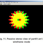
- There was an option for displaying the object in wire frame mode. The vertices of all the polygons are connected by lines form the wire frame. It clearly shows group of polygons. This can be done by the mode of display before drawing the object.
- If the mode is ‘GL_POINT’ then it displays only the vertices of all the triangles.
- Mouse interactions were defined for performing transformation functions like rotation, scaling and translation. The commands performs transformations are: glRotatef(), glScalef(), glTranslatef()
- Various combinations of light and material can be applied to test the appearance of model on the screen.
- Different camera views displays the model’s front, back, left, right, top, bottom and isometric view.
Stereo Vision
Stereoscopic display is a fundamental part of virtual reality. It is an effective way to enhance insight in 3D scientific visualization2. A common practice in stereoscopic systems is deliberate incorrect modeling of user eye separation. Eye separation is a necessary factor for the human visual system to fuse stereo image pairs into single 3D images. Image depth depends on the estimation of eye separation. This software demonstrates how a low end, inexpensive viewing technique can be used as a trick to produce the same effect as high end stereo viewing. This low cost stereo technique is called as passive stereo4.
The real trick is figuring out the best way to present the left and right eye images to just the left and right eyes, respectively7. In passive stereo technique to view the 3D scene Red-Blue Anaglyph is used. Left and right eye images are combined into a single image consisting of blues for the left eye portion of the scene, reds for the right eye portion of the scene, and shades of magenta for portions of the scene occupied by both images. The viewer wears a pair of glasses with red over the left eye and blue over the right eye.13 Each eyepiece causes the line work destined for the other eye meld into the background and causes line work destined for its own eye to appear black.
In this application 3D stereo vision is implemented by following the below given sequence,9
- Set the geometry for the view from left human eye
- Set the left eye rendering buffer
- Render the left eye image
- Set the geometry for the view from right human eye
- Set the right eye rendering buffer
- Render the right eye image
- Swap buffers
Snapshots
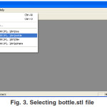
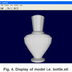
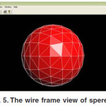
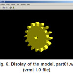
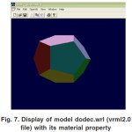
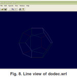
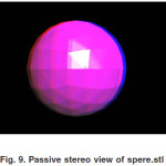
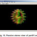
For testing the capability of the software, bottle.stl, spere.stl, part01.wrl, dodec.wrl files were given as input for the software. Fig 3 to Fig 11 gives the snapshots. Fig. 9, 10, 11 shows passive stereo image. This scene can be viewed with anaglyph (red-blue or red-green eye ware), which gives 3D effect.
Summary and Conclusion
This paper presented the representation of STL and VRML files in to the appropriate format for virtual reality/stereo visualization solution. The 3D visualization system provides simulation to enable designers to obtain a more realistic feeling. In manufacturing industries the visualization solutions are major tools for rapid prototyping. Rapid prototyping is the method for the creation of components derived from 3D CAD data. It enables engineer to troubleshoot the problems within existing designs and to significantly reduce the risk associated with developing the new designs. It helps the manufacturing industry to reengineer their product development practices in order to bring new, better-quality products to market faster, at a lower cost.
References
- Georges Fadel, Darren Crane, Larry Dooley, Robert Geist, “Support Structure Visualization in a Virtual Reality Environment”
- Runar Ostones, Victor Abbott, Samantha Lavender, “Visualization Techniques: An Overview – Part 2”, Part 1 was published in The Hydrographic Journal No 113, July 2004
- Sandy Ressler, “Applying Virtual Environments to Manufacturing”, Open Virtual Reality Testbed, January 1994
- Seth Abhishekh “A low cost virtual reality interface for CAD model manipulation and visualization”, Spring 2005
- F. Dai and P. Reindl, “Enabling digital mock up with virtual reality techniques – vision, concept demonstrator”, In Proceedings of 1996 ASME Design Engineering Technical Conference and Computers in Engineering, California, (1996).
- Filip Sixta, “VRML Parser in Java”
- Bruce Ricketts, VIZCAN Systems, “A White Paper on Passive Stereo”
- Antonino Gomes de S´a, Gabriel Zachmann, “Virtual Reality as a Tool for Verification of Assembly and Maintenance Process”
- R.Yaman, “Establishment and use of Virtual layouts for manufacturing”, Integrated Manufacturing Systems, 12(6) (2001).
- Nicolae Balc, R Ian Campbell, “From CAD and RP to Innovative Manufacturing”
- Rikk Carey, Gavin Bell- “The annotated VRML 97 Reference Manual”
- Mason Woo, Jackie Neiderr, Tom Davis. “OpenGL programming guide” The official guide to learning OpenGL.
- Tomi Engdahl, “3D glasses and other 3D display devices”
- http://en.wikipedia.org/wiki/STL_(file_format) – Information about STL files – the free encyclopedia on web
- http://www.techiwarehouse.com/cms/ engine.php?page_id=bb0d3668 – VRML Tutorial, Techi Warehouse
- Claire Knight, “Visualization Effectiveness” Published in CISST (2001).

This work is licensed under a Creative Commons Attribution 4.0 International License.