Fiber Bragg Grating (FBG) is Used as Modeling and Simulation for Temperature Sensor
Manish Saxena¹* and Anubhuti Khare²
¹EC Department BIST Bhopal, (India).
²Department of Electronics and Communication, University Institute of Technology, Rajeev Gandhi Technical University, Bhopal, (India).
Article Publishing History
Article Received on :
Article Accepted on :
Article Published :
Article Metrics
ABSTRACT:
This paper deals with mathematical modeling, design and application of Fiber Bragg Grating as temperature sensor .In this paper we used the MATLAB and filter characteristics simulation software as a tool for simulation results. The fabrication of Fiber Bragg Grating, their characteristics and fundamental properties are described. The reflectivity of FBG is described using simulation results. This paper also presents the simulation results of FBG as temperature and gas sensor. From the plotting analysis it can be concluded that for reduce the width of reflection spectrum we can take long grating.
KEYWORDS:
Fiber Bragg Grating; Grating Sensor; WDM; MATLAB; strain; Temperature; Runge Kutta algorithm
Copy the following to cite this article:
Saxena M, Khare A. Fiber Bragg Grating (FBG) is Used as Modeling and Simulation for Temperature Sensor. Orient. J. Comp. Sci. and Technol;3(1)
|
Copy the following to cite this URL:
Saxena M, Khare A. Fiber Bragg Grating (FBG) is Used as Modeling and Simulation for Temperature Sensor. Orient. J. Comp. Sci. and Technol;3(1). Available from: http://www.computerscijournal.org/?p=2211
|
Introduction
The refractive index and grating period are the important properties of Fiber Bragg Grating.so we will study the effect of refractive index of FBG and grating period in sensor application.A FBG is a periodic perturbation of refractive index along the fiber length which is formed by exposure of the core to an ultraviolet light.The first FBG demonstrated by Hill et al in 1978 the Canadian communication Research center,FBG have the advantage of low insertion loss, low cross talk, low light return loss, compact size, a periodically low cost.
The linear effect of FBG like dispersive and wavelength selective properties has been studied. It also have successfully implemented in optical signal processing devices in WDM network such as dispersion compensator, and filter. There have been many studies to develop technique to obtain the desired spectrum response of FBG by altering physical parameter such as induced index change,length, apodized period chirp and fringe tell.FBG are now commercial available and they have found key application in routing,filtering, control and application of optical signal and sensor technology.
In this paper an introduction of FBG is given which focus on the mathematical modeling of FBG by the help of simulation results we will able to provide the properties of FBG.
Mathematical Modeling Of Fbg
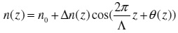
The Bragg scattering of waves in a waveguide occur when the refractive index vary in z direction given as.
if fiber is in a single mode operation, it support only fundamental mode. Which has two component propagating in opposite direction. These are v1 for forward propagating wave and v2 for backward propagating wave then compact mode equation
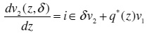
Where v1 and v2 are complex amplitude envelopes of waves and obtained by removal of the spatial dependence exp(±iπz/Λ) and q(z) defined as is complex coupling coefficient
Where δ the phase shift per unit length compared to the Bragg wavelength is is given as
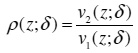
The reflection coefficient is given by defined Riccati equation
By calculating dp/dz and substituting dz and dv2/dz from coupled mode equation and we get well
defined Riccati equation
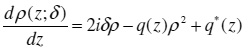
This differential equation can be solved for the relation of reflection coefficient r(δ)=ρ(0,δ) at the beginning of graing lengthL by using Runge Kutta Method 4th order and boundary condition. When the number of samples of is small, it is necessary to include an interpolation routine to increase the number of sample in order to reduce the error in the Runge Kutta algorithm
FBG as Temperature Sensor
Bragg grating wavelength λBcan be calculated using refractive index and grating period.The shift in due to change in strain and temperature is given as
∆λB = 2( Λ∂n/ ∂l + n∂Λ / ∂l) ∆l + 2( Λ∂n/ ∂T + n∂Λ / ∂T)∆T
Where T is the temperature and l is the length of starin effect, the second term of equation show the effect of temperature on FBG.The shift in Bragg wavelength due to thermal expansion change grating spacing and change in the index of refraction of refraction
∆λB = λB (a-ξ) ∆T
Where is called thermal expansion and having value approximately 0.55 × 10⁻⁶ for silica and ξ = (1/ n)(∂n / ∂T) is called thermo optics coefficient having value appx. 8.6 × 10⁻⁶ / 0C for Ge doped silica core fiber.
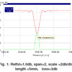
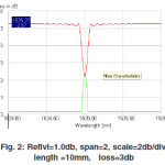
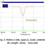
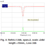
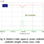
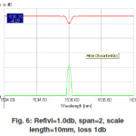
Simulation Results of Uniform Grating
The below given graph are of uniform Fiber Bragg Grating.These plots are drown at grating length at 5 mm & 10 mm and different transmission loss 1 dB,2dB,3dB. These plots show the different reflectivity at different loss and Bragg wavelength.
At the Bragg wavelength the reflection is highest, and before and after the reflection decrease in the form of sinc function and similar the transmission is highest at other than Bragg wavelength. At Bragg wavelength the transmission loss is highest.
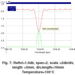
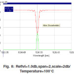
Result on Temperature
As we increase the temperature the Bragg wavelength shift to left or right depend on the value of temperature if the temperature is less than 0oC than shift to the right and if temperature is greater than zero than it shift to the left. Fiber Bragg grating based sensor can be used to measured the temperature 73K to 350K and this sensor have higher resolution, high accuracy and easy to use. The given plots are showing the spectrum of reflection and transmission. According to figure the reflection is highest at Bragg wavelength and at that point the transmission loss is high. these plot are drawn for 5 mm/10 mm length of grating.as we increase the length of grating the width of spectrum decrease its means for the low reflection we should use long grating.
Conclusion
Simulation results are taken for uniform grating, different length (5mm and 10mm), and different reflection loss (1db, 2db and 3db). Simulation results give spectral properties of grating for uniform grating and temperature effected grating.
This paper gives description based on modeling of FBG. From results we can conclude that for low loss and less reflection we must try to use long grating and FBG is suitable for using in temperature sensor. From the plots we can see that the transmission loss is high at Bragg wavelength and its shift to right when we use grating as temperature sensor.
Acknowledgements
Mrs. Anubhuti Khare one of the authors is indebted to Director UIT RGPV Bhopal for giving permission for sending the paper to the journal. Manish Saxena is also thankful to the Chairmen, Bansal Institute of Science & Technology Bhopal for giving permission to send the paper for publication. Last but not least I also thank to my family and all our colleagues of BIST, Bhopal for helping us while developing this paper.
References
- Bashir A.T.,Jalil Ali,Rosly A.R.”Fabrication of fiber bragg Grating by Phase mask and its sensing application”. Journal of Optoelectronics and Advanced material. 8(4): 1604-1609 (2006).
- Liu, Y. Advanced fibre gratings and their application. Ph.D. Thesis, Aston University. (2001).
- J. Canning, Fibre Gratings and Devices for Sensors and Lasers, Lasers and Photonics Reviews,2(4), 275-289, Wiley, USA (2008).
- Dasgupta Abhijit & Sirkis James S, “Importance of coatings to optical fiber sensors embedded in smart structures”, An Inst Aeronaut Astronaut J,30(5): 1337-1343,(1992).
- Fernandez Fernandez A., Brichard A., Berghmans F., “In Situ Measurement of Refractive Index Changes Induced by Gamma Radiation in Germanosilicate Fibers”, IEEE Photonics Technology Letters, 15(10), 1428 – 1430 (2003).
- François Ouellette, “Fiber Bragg Gratings”, Communications Research Center.
- Kashyap R., “Fiber Bragg Gratings”, Academic Press, pp. 458, (1999).
- Martelluci Sergio, Chester Arthur N & Mignani Anna Grazia, “Optical Sensors and Microsystems”, Kluwer Academic/Plenum Publishers, NY, (2000).

This work is licensed under a Creative Commons Attribution 4.0 International License.