Introduction
Exploration as well as upgradation to 5G mobile
wireless technologies have been the current topic of research in both the
academia and industries. Though Code-Division Multiple Access (CDMA) was used extensively
in the Third Generation (3G) technologies, it had certain disadvantages like
Inter-Symbol-Interferences and High power consumptions. The CDMA was replaced
with OFDM as it possessed higher ease of implementation, resistant to external
interference with faster high data-rate. The OFDM is a multicarrier orthogonal
digital communication scheme, it divides the whole available bandwidth into
many streams of low data rates that are then modulated simultaneously by
multiple carriers. The modulation schemes deployed defines the spectral
efficiency and application of the waveform in wireless communication standards.1
The OFDM enjoys superiority in a number of technological and performance aspects. To mention a few, it has lowest complexity when compared to other waveforms due to the use of Fast Fourier Transform (FFT) / Inverse Fast Fourier Transform (IFFT), highest bandwidth efficiency, higher resistance to frequency selective fading, exceptional symbol structure and simplified synchronization. The OFDM does possess two major drawbacks, very high Peak to Average Power Ratio and Out-Of-Band (OOB) emissions that significantly reduce system performance and throughput. Others include Cyclic Prefix and bigger side lobes that limits the spectrum efficiency. Even though OFDM marks a tremendous leap in the technological advancement in 4G, the above mentioned defects overshadows it to be deployed for 5G standards.
Research studies show the proposal and
development of other multicarrier waveforms in recent years to improve PAPR and
OOB emissions for 5G. This paper provides the flaws in the design of OFDM
system and the current research trend in this field. Section 2 provides the
historical development of OFDM. Section 3 briefly explains OFDM system model. The
problems and issues related with OFDM are discussed in Section 4. Finally,
Section 5 concludes with future scope.
Developments in OFDM
Classical Multicarrier Communication (MCC)
systems KINEPLEX and KATHRYN were initially developed by armed forces during
the 1950s. The OFDM in its initial stages lacked of technology to support high integrated
electronic circuitry, thus was not deployed for broadband services. The OFDM transmitted
data on non-overlapping orthogonal signals that were band limited in nature.
The circuitry required the need for analog filters of larger bandwidth with
severe cut-off frequency. Subcarrier were recovered at the receiving end with
inter-carrier interference. Hence, OFDM had not gained much attention then.
But, during the 1960s, several studies2 – 4 were dedicated to
develop overlapped band-limited orthogonal signals. Research study5
developed a multicarrier communication system deploying Quadrature Amplitude
Modulation in OFDM with time-staggered carriers. The research work of Chang3
and other scholars in 1966 dealt with the fundamental formulation of OFDM
concept that had brought RF communication standards to a new realm.
In January 1970, the concept of OFDM was the
first name patented in United States of America.6 In 1971,
implementation of Discrete Fourier Transform (DFT)/Inverse Discrete Fourier
Transform (IDFT) with integrated circuit technology to transmit orthogonal
signals was brought OFDM to lime light.7-8 Subcarrier oscillators at
the transmitter and receiver were significantly reduced further enhancing the
ease of the implementation in OFDM at reduced cost.
During 1980s research works proposed the
structure of DFT for OFDM to be used specially for high-speed digital wireless communication.
Among those works, there was a work of Hirosaki,9 who proposed
enhanced work of Saltzberg’s OFDM/OQAM system, and also a US patent in June 1980
that deployed OFDM in high speed modems.10 Further, in 1985, Cimini11
delivered simulation analysis on OFDM in mobile communication and critically
praised its impressive performance. Semiconductor industries’ revolutionary
growth had given much opportunities and challenges.12 – 15
The Broadband applications and evolution in Very-Large-Scale Integrated circuits (VLSI) and Complementary Metal–Oxide–Semiconductor (CMOS) chips in the 1990s, further dominated by OFDM in the market. The acceptance of OFDM by the European Digital Audio Broadcasting (DAB) standard defies the milestone achievement for its widespread commercial implementation in all domains. The suitability of OFDM system in different environments experimentally over frequency selective channel with Rayleigh fading was the scope of the research which were presented by researchers.16-18 Further, the research works19-21 conducted the OFDM system performance in different channel conditions with offset in frequency. To brief it all, this technology from 1960s, improved from a mere mathematical model to implementation in the 90s, thanks to technological progress implementing DFT in digital circuits. The 4G technology Long Term Evolution (LTE) deploys OFDM wherein large closely set orthogonal subcarriers carry data.22 Even though sidebands from carriers overlap, the received signal is detected without interference due to their orthogonal positioning with each other. Guard bands are not needed to separate subcarriers. A cyclic prefix is added to the end of each OFDM symbol to maintain he orthogonality in the sub-carriers.
Modelling of OFDM System
The OFDM
make use of a sophisticated divide-and-conquer methodology to transmit high
speed frequency-selective channels.23 It is a multicarrier block
modulation scheme wherein the whole available bandwidth is divided into
different sequence of symbols of low data rates and then modulated
simultaneously by multiple partially overlapped subcarriers which are
orthogonal to each other and transmitted in parallel form to achieve high
aggregate data rates and bandwidth efficiency. Flat frequency response is
generated in individual sub-carriers with constricted bandwidth in sub-channel,
avoiding complex equalization in time-domain. Thus, frequency-selective channel
is transformed into individual flat-fading channel enhancing receiver signal9
robust to multi-path fading and bit error rate. Orthogonality5 in
the carriers also eliminates the inter-carrier interference. Insertion of
spectral guard bands for partially overlapped sub-carriers provides higher spectral
efficiency with respect to conventional Frequency Division Multiplexing (FDM). Digital
data is transformed and mapped in accordance to sub-carrier amplitude and phase.
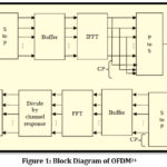
Spectral data in mapped to the time domain using Inverse Discrete Fourier Transform.
The implementation of IFFT in place of IDFT further adds to computational
efficiency at the cost slight increase in operational infrastructure. Hence IFFT/FFT
is now deployed in all practical systems. Reverse operation is performed at the
receiver section, where RF signals are added to baseband proceeded by FFT that analyses
the the received signal in frequency domain. Digital data is generated out of
the subcarrier’s amplitude and phase. FFT and IFFT are complementary in nature24
(see Figure 1).
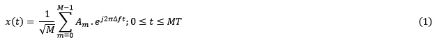
Explaining mathematically,25 high-data-rate bit stream of frequency bandwidth B is de-multiplexed into M lower-rate streams that modulate M equally spaced subcarriers that are non-overlapped orthogonal where B=M∆f and ∆f=1⁄MT. Each sub-carrier of a given OFDM symbol is modulated by a known constellation. The input data symbols in frequency domain A= [A0,A1,A2,….,Am-1) ]T where An characterizes complex information of the mth sub-channel. After performing M length IFFT on a’,we obtain time domain OFDM sequences y= [a,a1,a2,….,am-1]T where Δf = 1 / MT the subcarrier spacing6 is.
1Multi-level modulation,26 M-ary QAM, may be deployed in Single-Carrier modulation, Frequency Division Multiplexing and OFDM. If we consider f1 be the sinusoidal complex Quadrature Amplitude Modulated character, Xi – jYi, where values of Xi andYi depends on constellation of QAM, signal can be expressed as:

In-phase and quadrature portions of signal are denoted by the two terms respectively a1(t) and a2(t), where a2(t) is signal modulated by QAM on sub-carrier f2 can be ensured to be orthogonal by satisfying the following condition.

Condition must validate for all an (t); am (t), n = 0,1,2,3…N-1;m=0,1,2,3…N-1;n≠m. Validation of the condition ensures generation of orthogonal OFDM signals. It satisfies only when the subcarrier frequencies are integer multiples over the symbol time as

In Equation (4), the term denotes different radio frequencies.
Substituting Equation (2) into (3) for all Sn (t), Sm (t), n≠m and, it can readily be shown that all subcarriers will indeed be orthogonal to each other, in the same frequency space without interfering stating the possibility of partially overlap of OFDM subcarriers in frequency devoid of interference. Adding equations (2), (4) combines to give us the complete electrical OFDM signal as follows in Equation (5) wherein g(t) represents impulse response of baseband pulse shaping filter.

5G and OFDM – Drawbacks and Issues
The
big difference between 5G and its previous generations lies in the fact that 3G
and 4G focused high mobility to be an afterthought. However, in 5G
communication high mobility is treated as an integral part of communication and
network architecture design. Even though systems using OFDM have grown importance
in recent years, OFDM faces many challenges in the aspect of its adoption in
wireless networks. One of the biggest hurdles in OFDM is PAPR, which
significantly reduces the performance, spectral characteristics, and efficiency.
Literature review27 reveals significant drawbacks in OFDM. Firstly,
PAPR problem arises when sinusoidal signals of OFDM subcarriers constructively
add in the time domain, resulting in sharp amplitude peaks higher than average
amplitude of the signal. Also use of cyclic prefix or guard band, 10% of the
bits are repeated which decreases spectral efficiency. Secondly, OFDM displays major
amplitude fluctuations over time, generating a high peak-to-average power ratio.
This is due to nonlinearity in amplifier at the transmitter. Thirdly, Gaussian amplitude distribution of
the OFDM signal with large number of subcarriers results in transmitted signal
with high peaks. Fourthly, Carrier and timing synchronization are challenging
tasks. Lastly, Carrier Aggregation in OFDM-based systems that generated when digital
data is transmitted in non-contiguous frequency ranges. Further, significant
out of band noise is introduced in these systems, that pick-up interference
from nearby channels. Because of these significant drawbacks, it does not
appear that OFDM would continue to serve as a proficient technique for 5G
communications.
Peak to Average Power Ratio (PAPR)
The OFDM signal is made up of several modulated sub-channels. In a situation, where channels to get added in phase, a sudden shoot up in output envelope which causes a ‘peak’ power. The peak power is produced times its usual power bringing about PAPR.28 The PAPR is the ratio of peak power to the average power of a signal. It is expressed in the units of dB. Due to high peaks in a signal, the power amplifier goes to its non-linear region.
Since PAPR requires increased complex Digital to Analog Convertor and High Power Amplifier to evade clipping of amplitude. Hence, power consumption and transceiver cost increases. Orthogonality is destroyed between carriers introducing intermodulation distortion. Adjacent channel interference increases degrading Bit Error Rate (BER) and battery life of mobile terminal. PAPR is more disastrous in uplink due to limited coverage, range and battery of mobile terminal. Therefore PAPR ought to be reduced for making the system efficient. Coverage and reliable power output remains the critical focus of study for tactical communications.22 The peak to average power ratio for a signal is defined as,

Equation (7) describes OFDM signal as a sum of several sub-carriers saperated by frequency 1/t. Equations (8) and (9) denote the peak and average power of the output envelope respectively.

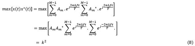
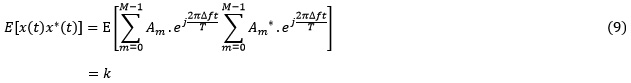
Thus , PAPR of an OFDM signal with K subcarriers can be defined as:

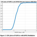
The
corresponding matlab script to simulate the average PAPR of an OFDM transmit
waveform using BPSK modulator that contains 52 sub-carriers. In that case, the
maximum expected PAPR should be 52 that amounts to 17dB.
Size_of_IFFT = 64;
No_of_Subcarriers = [-26:-1 1:26];
No_of_Bit = 10000;
ip = rand(1, No_of_Bit) > 0.5;
no_of_Bits_Per_Symbol = 52;
no_of_Symbols = ceil(No_of_Bit
/no_of_Bits_Per_Symbol);
% In BPSK modulation, bit0 is assigned level –>
-1; bit1 is assigned the level –> +1
ipMod = 2*ip – 1;
ipMod = [ipMod zeros(1, no_of_Bits_Per_Symbol*
no_of_Symbols – No_of_Bit)];
ipMod = reshape(ipMod, no_of_Symbols,
no_of_Bits_Per_Symbol);
st = []; % empty vector
for ii = 1: no_of_Symbols
input_of_iFFT = zeros(1, Size_of_IFFT);
input_of_iFFT
(No_of_Subcarriers + Size_of_IFFT/2+1) = ipMod(ii,:);
input_of_iFFT =
fftshift(input_of_iFFT);
output_of_iFFT =
64*ifft(input_of_iFFT, Size_of_IFFT);
output_of_iFFT_with_CP =
[output_of_iFFT (49:64) output_of_iFFT];
% To compute the peak to
average power ratio
Mean_Square_power =
output_of_iFFT * output_of_iFFT’/length(output_of_iFFT);
Peak_Value_power =
max(output_of_iFFT.*conj(output_of_iFFT));
Papr_value(ii) =
Peak_Value_power / Mean_Square_power;
st = [st
output_of_iFFT_with_CP];
end
close all
papr_in_dB = 10*log10(Papr_value);
[n x] = hist(papr_in_dB,[0:0.5:15]);
plot(x,cumsum(n)/ no_of_Symbols,’LineWidth’,4)
xlabel(‘PAPR Value, x dB’)
ylabel(‘Probability of occurance, X <=x’)
title(‘CDF plots of PAPR tx with BPSK Modulator
based on IEEE 802.11a’)
grid on
The corresponding CDF plot obtained is as follows. Its states that the PAPR varies around +3.5dB to a extreme limit of 10dB.
The PAPR
reduction technique in commercial communication structures is vital to save
power and enhance coverage gain. Considering the above facts, the sole purpose
in the implementation of real time OFDM must be to reduce high PAPR. Research
studies have taken the current imminent study in a vigorous manner and
recommended various approaches. Waveform is the fundamental issue for 5G
mm-wave communication. Key Performance Indicators (KPIs) such as computational
complexity, filter length, PAPR, spectral efficiency and latency assess the 5G
waveform candidates. An ideal waveform
primarily has very low PAPR, very high
spectral efficiency and data rate to allow power amplifier design; robust to
Doppler shift and support asynchronous transmission. The current cutting edge
research progresses towards reduction in PAPR in the 5G waveforms candidates
that can be classified into two categories I.e Single carrier Waveforms and
multi-carrier waveforms. Single carrier transmission uses single carrier is
used to carry the information with broad spectrum. Multi-Carrier transmission
uses multiple carriers at different frequencies, sending some of
the bits on each channel. An in-depth survey in the following research papers9,
18, 28, and 29 explains the differences between Single carrier and
Multiple Carrier waveforms which is explicity explained in Tables I, II.
Table I:
Advantages of Single Carrier vs Multicarrier Wavefroms
| Advantages | SC Waveforms | MCM Waveforms |
| PAPR | Low | Very High |
| Code Rate | Very High | Low |
| Battery Life | Extended | Less |
| Synchronization | Simple | Complex |
Table II: Disadvantages of Single Carrier vs Multicarrier Wavefroms
| Limitations | SC Waveforms | MCM Waveforms |
| Complexity | High | Moderate |
| Resistance to multi-path Fading | Poor | Excellent |
| Phase noise | Less Susceptible | More susceptible |
| Spectral Efficiency & Coverage | Low | High |
| MIMO compatibility [30,31] | Low to moderate | Very high |
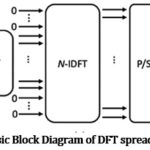
Because Single Carrier Wavefroms has a very low PAPR, and extended battery life, current 4G LTE uses Discrete Fourier Transform spread OFDM (DFT-S-OFDM), a low PAPR SC variant of OFDM30 – 33 for uplink communications and LTE-OFDM for downlink communication to reduce overall power consumption and increase coverage range. There lies two major future trends for conducting research in this domain. Firstly major research direction is the development of low-complexity OFDM-like multicarrier waveforms for downlink communication and variants of DFT-s-OFDM single carrier waveforms for uplink communication that derive efficient PAPR reduction in 5G.34 – 38 The Single Carrier waveform include DFT-s-OFDM family such as Zero-Tail- (ZT) DFT-s-OFDM, Unique Word (UW) DFT-s-OFDM, Differential-QAM, Constrained Envelope-CPM-SC as well as DFT-s-FBMC and DFT-s-UFMC to name a few. DFT-s – Waveform unlike conventional OFDM first spread the input data with DFT block, then de-spread with IDFT block as shown in Figure 3. This simple architecture achieves major reduction in power consumption.
The
Multi-Carrier waveforms consists of
Cyclic Prefix OFDM (CP)-OFDM, Unique-Word OFDM (UW)-OFDM, Universal-Filtered
OFDM (UF)-OFDM, Windowed-OFDM (W-OFDM), Filter Bank Multicarrier (FBMC), and
Generalized-FDM (GFMC) among others. Secondly major research direction is the
impemention of PAPR reduction methods for the above mentioned waveform variants
to achieve desired results.
Conclusion and Future Scope
This
paper presents a complete summary of OFDM, focusing the following issues such
as technological ideologies, real-world dominance and challenges, current
advancement and upcoming exploration in 5G standard. In overall, OFDM cannot be
considered for 5G due to its serious drawbacks of transmitting highly
correlated signals with very high PAPR. PAPR reduction is only possible at
increased transmission power, reduced data loss, low BER performance, computational
complexity. Hence, the subject of PAPR reduction is of eminent importance as
the upcoming wireless standards are expected to develop new waveform candidates
to eliminate the drawbacks of OFDM with better PAPR reduction.
Acknowledgements
The authors would like to express their great
appreciations and gratitude to Koneru Lakshmaiah University, Vijayawada, A.P.,
India and Sultan Qaboos University, Muscat, Sultanate of Oman for providing
research facilities, technical supports and research environment that enabled
us to complete this research task.
Conflict
of Interest
All
authors the authors declare that there is no conflict of interest.
Funding Source
This
research received no external funding.
Reference
- Chen, D.; Tian, Y.; Qu, D.; Jiang, T. OQAM-OFDM For Wireless Communications In Future Internet Of Things: A Survey On Key Technologies And Challenges. IEEE Internet Of Things Journal, Volume 5 (5), 2018, Pp. 3788 – 3809.
CrossRef - Chang, R. W. Synthfesis Of Band-Limited Orthogonal Signals For Multichannel Data Transmission, Bell Syst. Tech. J., Volume 45, 1966, Pp. 1775 – 1796.
CrossRef - Chang, R. W.; Gibby, R. A. A Theoretical Study Of Performance Of An Orthogonal Multiplexing Data Transmission Scheme, IEEE Trans. Commun. Tech., Volume COM-16, 1968. Pp. 529 – 540.
CrossRef - Saltzberg, B. R. Performance Of An Efficient Parallel Data Transmission System, IEEE Trans. Commun. Tech., Volume COM-15, 1967, Pp. 805 – 813.
CrossRef - Marmuth, H. F. On The Transmission Of Information By Orthogonal Time Functions, Alee Trans. (Communication And Electronics), Volume 79, 1960, Pp. 248 – 255.
CrossRef - Orthogonal Frequency Division Multiplexing, U.S. Patent No. 3488445, Filed Nov. 14, 1966, Issued On Jan. 6, 1970.
- Weinstein, S. B.; Ebert, P. M. Data Transmission By Frequency-Division Multiplexing Using The Discrete Fourier Transform, IEEE Trans. Commun. Tech., Volume COM-19, 1971, Pp. 628 – 634.
CrossRef - Ghani F.; Ahmad, A. Signal Design And Detection For A Class Of CDM Data Transmission System For Use Over Switched Telephone Networks, Proceedings Of IEEE 23rd Midwest Symposium On Circuits And Systems (CAS), Held At University Of Toledo (Ohio, USA), Aug.4 – 5, 1980, Pp. 7 – 12.
- Hirosaki, B. An Analysis of Automatic Equalizers For Orthogonally Multiplexed QAM Systems, IEEE Trans. Commun., Volume COM-28, 1980, Pp. 73 – 83.
CrossRef - Keasler, W. E.; Bitzer, D. L. High Speed Modem Suitable For Operating With A Switched Network, U. S. Patent No. 4206320, June 1980.
- Cimini, L. J. Analysis And Simulation Of A Digital Mobile Channel Using Orthogonal Frequency Division Multiplexing, IEEE Trans. Commun., Volume COM-33 (7), 1985, Pp. 665 – 675.
CrossRef - Elgawi, O; Mutawa, A. M.; Ahmad, A. Energy-Efficient Embedded Inference Of Svms On FPGA, IEEE Computer Society Annual Symposium On VLSI, To Be Held At Miami, Florida, USA, 15-17 July 2019, Pp. 1 – 5.
- Ahmad, A. (Keynote/Invited – Talk). Reliable And Fault Tolerant Systems On Chip Through Design For Testability”, IEEE Conference: 2019 Amity International Conference On Artificial Intelligence – (AICAI’19), Amity University, Int’l Academic City, Dubai, UAE, Feb. 4 – 7, 2019, Pp. 50 – 53.
CrossRef - Ahmad, A. (Keynote/Invited – Talk). Challenges For Test And Fault-Tolerance Due To Convergence Of Electronics, Semiconductor Systems And Computing, IEEE Conference: 2017 International Conference On Infocom Technologies And Unmanned Systems (Trends And Future Directions) (ICTUS), Amity University, Int’l Academic City, Dubai, UAE, 18 – 20 Dec. 2017, Pp. 64 – 68.
CrossRef - Ahmad, A. Testing Of Complex Integrated Circuits (Ics) – The Bottlenecks And Solutions, Asian Journal Of Information Technology, Volume 4 (9): 2005, Pp. 816 – 822, 2005.
- Bingham, J. A. C. Multicarrier Modulation For Data Transmission: An Idea Whose Time Has Come, IEEE Commun. Mag., Volume 28: 1990, Pp. 5 – 14.
CrossRef - Casas, E. F.; Cyril Lung. OFDM For Data Communication Over Mobile Radio FM Channels-Part I: Analysis And Experimental Results, IEEE Trans. Commun., Volume 39 (5), 1991, Pp. 783 – 793.
CrossRef - Casas, E. F.; Cyril Lung. OFDM For Data Communication Over Mobile Radio FM Channels-Part II: Performance Improvement, IEEE Trans. Commun., Volume 40 (4): 1992; Pp. 680 -683.
CrossRef - Sathananthan, K.; Tellambura, C. Probability Of Error Calculation Of OFDM Systems With Frequency Offset, IEEE Trans. On Commun. Volume 49 (11): 2001; Pp. 1884-1888.
CrossRef - Rugini, L.; Banelli, P. BER Of OFDM Systems Impaired By Carrier Frequency Offset In Multipath Fading Channels, IEEE Trans. On Wireless Commun., Volume 4 (5): 2005; Pp. 2279 – 2288.
CrossRef - Dharmawansa, P.; Rajatheva, N.; Minn, H. An Exact Error Probability Analysis Of OFDM Systems With Frequency Offset, IEEE Trans. Commun., Volume 57 (1): 2009; Pp. 26-31.
CrossRef - Sandoval, F.; Poitau, G.; Gagnon, F. Hybrid Peak-To-Average Power Ratio Reduction Techniques: Review And Performance Comparison, IEEE Access, 5, 2017, Pp. 27145 -27161.
CrossRef - Blouza, S.; Karaki, J.; Brochier, N.; Le Rouzic, E.; Pincemin, E.; Cousin, B. Multi-Band OFDM For Optical Networking, IEEE EUROCON – International Conference On Computer As A Tool, 2011.
CrossRef - Ghassan M. T. A. Orthogonal Frequency Division Multiplexing Theory And Challenges, University Of Khartoum Engineering Journal, Volume 1 (2), 2014, Pp. 1 – 8.
- Goebel, B.; Hellerbrand, S.; Haufe, N.; Hanik, N. PAPR Reduction Techniques For Coherent Optical OFDM Transmission, 11th International Conference On Transparent Optical Networks, 2009. Doi:10.1109/Icton.2009.5184979
CrossRef - Cvijetic, N. OFDM For Next-Generation Optical Access Networks. Journal Of Lightwave Technology, Volume 30 (4): 2012; Pp. 384 – 398.
CrossRef - Wang, Z.; Sun, E; Zhang, Y. An Overview Of Peak-To-Average Power Ratio Reduction Techniques For OFDM Signals, International Journal Of Mobile Network Communications & Telematics, Volume 6 (3), 2016, Pp. 1 – 20.
CrossRef - Zaidi, A. A., Luo, J., Gerzaguet, R.; Wolfgang, A.; Weiler, R. J.; Vihriala, J.; Miao, H. A Preliminary Study On Waveform Candidates For 5G Mobile Radio Communications Above 6 Ghz, 2016 IEEE 83rd Vehicular Technology Conference (VTC Spring). Doi:10.1109/Vtcspring.2016.7504096
CrossRef - Elavarasan, P.; Nagarajan, G. A Summarization On PAPR Techniques For OFDM Systems, Journal Of The Institution Of Engineers, India. Series B, Volume 96 (4), 2014, Pp.381-389.
CrossRef - Khan, K.A.; Ahmad, A. On Multi-Port Active RC Synthesis Of A Current Gain Matrix With Grounded Ports, Journal Of IETE, Volume 25 (11): Pp. 445 – 449, Taylor & Francis Online (11 July, 2015). Http://Dx.Doi.Org/10.1080/03772063.1979.11451977 Http://Www.Tandfonline.Com/Doi/Abs/10.1080/03772063.1979.11451977
CrossRef - Khan, K.A.; Ahmad, A. Active RC Multiport Synthesis Of A Current Gain Matrix – A Computer Aided Design, Proceedings Of 14th National System Conference (NSC-90), Held At Aligarh (India), March 12 – 14, 1991, Pp. 21 – 24.
- Khan, K.A.; Ahmad, A. Active RC Multi-Port Synthesis Of A Transfer Admittance Matrix With Minimum Number Of Capacitors – A Computer Aided Design, Proceedings Of IEEE International Conference On Signals & Systems, Held At Al-Ain (UAE), Jan.29 – 31, 1990, Volume 2, Pp. 63 – 74.
- Khan, K.A.; Ahmad, A.Active RC Multi-Port Synthesis Of A Transfer Admittance Matrix With Minimum Number Of Capacitors, Proceedings Of 14th Annual Allerton Conference On Circuits And Systems (CAS), Held At University Of Illinois (Urbana-Champaign, USA), Sept. 29 – Oct.1, 1976, Pp. 569 – 575.
- Yekani, Amin, and Leslie A. Rusch. “Numerical Study of a Hybrid Optical DMT/DFT-S QAM Modulation.” Journal of Lightwave Technology, vol. 37, no. 3, 1 Feb. 2019, pp. 815–823, 10.1109/jlt.2018.2881380. Accessed 4 Aug. 2019.
CrossRef - Hossain, Md. Rabiul, and Kazi Tanvir Ahmmed. “Non-Linear Companding Based Hybrid PAPR Reduction Approach for DCT-SCFDMA System.” IET Communications, vol. 12, no. 12, 31 July 2018, pp. 1468–1476, 10.1049/iet-com.2017.0921. Accessed 4 Aug. 2019.
CrossRef - Nissel, Ronald, and Markus Rupp. “Pruned DFT-Spread FBMC: Low PAPR, Low Latency, High Spectral Efficiency.” IEEE Transactions on Communications, vol. 66, no. 10, Oct. 2018, pp. 4811–4825, 10.1109/tcomm.2018.2837130. Accessed 4 Aug. 2019.
CrossRef - Na, Donj-jun, and Kwonhue Choi. “New DFT-Spread Filter Bank Based Multi-Carrier Transmission.” The Journal of Korean Institute of Communications and Information Sciences, vol. 42, no. 7, 31 July 2017, pp. 1297–1305, 10.7840/kics.2017.42.7.1297.
CrossRef - An, Changyoung, and Heung-Gyoon Ryu. “PAPR Evaluation and Analysis of Candidate Waveforms Using DFT Spreading for 5G Mobile Communications.” The Journal of Korean Institute of Electromagnetic Engineering and Science, vol. 26, no. 12, 31 Dec. 2015, pp. 1091–1099, 10.5515/kjkiees.2015.26.12.1091.
CrossRef
Abbreviations and Symbols used in this Paper
|
3G
|
Third
Generation
|
|
4G
|
Fourth
Generation
|
|
5G
|
Fifth
Generation
|
|
BER
|
Bit Error Rate
|
|
CE
|
Constrained
Envelope
|
|
CDMA
|
Code-Division
Multiple Access
|
|
CMOS
|
Complementary
Metal–Oxide–Semiconductor
|
|
CP
|
Cyclic Prefix
|
|
CPM
|
Continuous-Phase-Modulation
|
|
D
|
Differential
|
|
DAB
|
Digital Audio
Broadcasting standard
|
|
DAC
|
Digital to
Analog Convertor
|
|
DFT
|
Discrete
Fourier Transform
|
|
DFTS
|
Discrete
Fourier Transform Spread
|
|
FFT
|
Fast Fourier
Transform
|
|
FB
|
Filter Bank
Multi-Carrier
|
|
FBMC
|
Filter Bank
Multi-Carrier
|
|
FDE
|
Frequency
Domain Equalization
|
|
FDM
|
Frequency
Division Multiplexing
|
|
FDMA
|
Frequency
Division Multiple Access
|
|
FFT
|
Fast Fourier
Transform
|
|
G
|
Generalized
|
|
HPA
|
High Power
Amplifier
|
|
IDFT
|
Inverse
Discrete Fourier Transform
|
|
IFFT
|
Inverse Fast
Fourier Transform
|
|
ISI
|
Inter-Symbol
Interference
|
|
KPIs
|
Key Performance
Indicators
|
|
LTE
|
Long Term
Evolution
|
|
MC
|
Multi-Carrier
|
|
MCC
|
Multi-Carrier
Communication
|
|
MCM
|
Multi-Carrier
Modulation
|
|
MIMO
|
Multiple-Input
Multiple-Output
|
|
OFDM
|
Orthogonal
Frequency Division Multiplexing
|
|
O-QAM
|
Orthogonal
time-staggered QAM
|
|
OOB
|
Out-Of-Band
|
|
P
|
Pulse-shaped
|
|
PAPR
|
Peak to-
Average Power Ratio
|
|
QAM
|
Quadrature
Amplitude Modulation
|
|
RF
|
Radio Frequency
|
|
SC
|
Single Carrier
|
|
UF
|
Universal
Filtered
|
|
UFMC
|
Universal
Filtered Multi-Carrier
|
|
UW
|
Unique Word
|
|
VLSI
|
Very Large
Scale Integration
|
|
W
|
Windowed
|
|
ZT
|
Zero-Tail
|

This work is licensed under a Creative Commons Attribution 4.0 International License.
 , Penke Satyanarayana1 and Afaq Ahmad2*