What Causes to Tune a Condition of Exactly Identical Fault-Masks Behaviors in an LFSR based BIST Methodology
A. Ahmad*  , D. Al Abri, S. S. Al Busaidi and M. M. Bait‐Suwailam
Department of Electrical and Computer Engineering, College of Engineering, Sultan Qaboos University, P. O. Box 33, Postal Code 123; Muscat, Sultanate of Oman.
Corresponding Author Email: afaq@squ.edu.om
DOI : http://dx.doi.org/10.13005/ojcst/10.04.02
Article Publishing History
Article Received on : 12-12-2017
Article Accepted on : 23-12-2017
Article Published : 25 Dec 2017
Article Metrics
ABSTRACT:
The authors show that in a Built-In Self-Test (BIST) technique, based on linear-feedback shift registers, when the feedback connections in pseudo-random test-sequence generator and signature analyzer are images of each other and corresponds to primitive characteristic polynomial then behaviors of faults masking remains identical. The simulation results of single stuck-at faults show how the use of such feedback connections in pseudo-random test-sequence generator and signature analyzer yields to mask the same faults.
KEYWORDS:
Built–In Self-Test; Characteristic Polynomial; Pseudo-Random Test-Sequence Generators; Signature Analyzer; Terms—Linear Feedback Shift Register; Test Pattern
Copy the following to cite this article:
Ahmad A, Al Abri D, Al Busaidi S. S, Bait‐Suwailam M. M. What Causes to Tune a Condition of Exactly Identical Fault-Masks Behaviors in an LFSR based BIST Methodology. Orient.J. Comp. Sci. and Technol;10(4)
|
Copy the following to cite this URL:
Ahmad A, Al Abri D, Al Busaidi S. S, Bait‐Suwailam M. M. What Causes to Tune a Condition of Exactly Identical Fault-Masks Behaviors in an LFSR based BIST Methodology. Orient. J. Comp. Sci. and Technol;10(4). Available from: http://www.computerscijournal.org/?p=7309
|
Introduction
n recent years, numerous Built-In Self-Test (BIST) systems have been proposed just because of its gaining acceptance in the VLSI industry due to its popular enormous advantages1–6. With BIST methodology, there is no need to use external test equipment since a self-testable circuitry is built on the chip itself. The BIST technique usually combines a built-in Pseudo-Random Test-Sequence (PRTS) generation with an output response analyzer. This methodology relief us from the complex task of test-sequence generation and decreases the storage requirements of test-sequences and response data. Since, in BIST methodology, test-signals are applied using normal clock rate, therefore, testing of a chip that designed with BIST methodology can be performed at-speed. Additionally, because the test resources are available during the entire life of the chip, thus, diagnosis and maintenance of the systems can be greatly simplified.
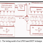
Figure 1 depicts a general Linear Feedback Shift Registers (LFSRs) based test model for BIST technique. In particular, PRTS generation followed by the compression of response data by Signature Analyzer (SA) has become a standard form of testing technique in BIST environment. LFSRs are usually used in this form of testing in both Pseudo-Random Test-Sequence Generators (PRTSGs) as well as in SAs. Undoubtedly, LFSR-based PRTS generation is known to be an extremely simple method of generating a required number of test-sequences. Although, various estimation and trade-off schemes have been floated to determine the length of the test-sequences that will be required to achieve the desired fault coverage. However, these schemes usually give a number that is only an estimate and sometimes too large. To overcome these problems, a ‘divide-and-conquer’ approach for testing of large sizes of circuits has been proposed7–15. The philosophy behind the divide-and-conquer approach of testing is to apply either the exhaustive test-stimuli or maximal length PRTSs to the different segmented units of the Digital Circuit Under Test (DCUT).
An added difficulty arises when the resulting circuit response data is compressed into small signature using the SA. Although, the signature analysis scheme which is easily implemented by LFSRs, but it leads to loss of information, due to the erroneous response patterns that get compressed into the same signature as the fault-free signature. Thus, some of the faults might go undetected due to this fault-masking phenomenon and resulting to reduce the fault coverage of the DCUT. A Method to determine the extent of fault masking and its phenomenon in any DCUT is not readily available. However, many approaches have been suggested1–22 to analyze and improve the basic signature analysis schemes. The use of primitive polynomials in SA with some restrictions7,15,17,20–22 along with obtaining multiple signatures with the use of different feedback connections in LFSRs of PRTSG as well as of SA1,3-5,18,19 can prove a better solution for minimizing the fault-masks.
Thus, in LFSR based BIST test methodology, to achieve better fault coverage for a DCUT the following suggestions have been given by the researchers.
Use of those feedback connections in PRTSGs, which correspond to primitive polynomials to generate maximal length PRTSs.
Use of those feedback connections in SAs, which correspond to primitive polynomials.
Use of multiple feedback connections in the LFSRs of PRTSG as well as of the SA.
However, this paper reports and demonstrates an interesting and peculiar result of a simulation study of an LFSR based testing technique where the feedback connections of LFSRs used in PRTSG as well as of SA correspond to primitive polynomials of order n, for an n-input DCUT. It is investigated through the compiled results of this study that when the feedback connections of PRTSs and of SAs are images of each other than behaviors of faults masking remains identical and hence, not enhancing the fault coverage due to the changes of the feedback connections.
Simulation Experiment
The testing model employed in our simulation experiment is the same as the standard BIST models used in the studies.1-22 The BIST standard model is shown in Figure 1. Various n-input combinational circuits summarized in Table I, have been simulated using the referred IC’s manufacturer’s logical diagrams with gate level description. In the simulation procedure, to get the single bit stream of circuit response (CR) from multiple output circuits, an appropriate tree of Exclusive-ORs is used.
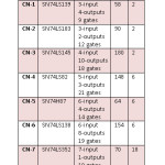 |
Table 1: Summary of Simulated Circuits. CN: Circuit Number; CS: Circuit Specification; NFI: Number of Faults Injected; NPI: Number of Possible Feedback Connections Corresponding To Primitive Polynomials
Click here to View table
|
A single stuck-at fault model is assumed where s-a-0 and s-a-1 faults are postulated on each individual connecting lines (out of the total number, NC), of the DCUT. Each possible image pairs of feedback connections (F, FI) as described by Equations (1) and (2) are used in the simulation.
F = {fi0, fi1, fi2, . . . , fij, . . ., fi(n-1), fin} (1)
FI = {fi0, fi(n-1), fi(n-2), .., fi(n-j), . . , fi(n-n+1) , fin} (2)
The feedback connections (F, FI) correspond to primitive polynomials of order n (out of the set of the total such possible feedback connections, NFB = 2n-1; 1£ i £ NFB), are used to equip the LFSRs of PRTSG and of SA respectively.
Finally, the simulation procedure collects the identification list of masked faults for each set of image pairs of feedback connections of LFSRs. For the study of an n-input combinational circuit, the adopted formal procedure to compile the list of identified masked faults for each set of image pairs of feedback connections of LFSRs, is summarized in the form of an algorithm and is given below:
Algorithm
(For a circuit segment’s unit under test having an n-input).
Step 0
Choose the ith (i = 1 to NFB) feedback connection (fi0 , fi1 , . . . , fij , . . . , fi(n-1) , fin) for the LFSRs used in PRTSG (say; FBTI) such that it corresponds to primitive polynomial.
Step 1
Generate the image of FBTI and equip the LFSRs of SA with these feedback connections (say; FBSI).
Step 2
Load LFSR used in PRTSG with initial state (other than all 0s initial state vectors).
Step 3
Generate PRTS of length 2n-1.
Step 4
Evaluate DCUT’s response CRk (k = 0 to 2 NC).
Step 5
Load LFSR used in SA with initial state (all 0s).
Step 6
Choose DCUT’s response CRk (CR0 is fault-free response, CR1 is the response under condition when connecting line #1 is subjected to s-a-0 fault, CR2 is the response under condition when connecting line #1 is subjected to s-a-1 fault. Similarly, CR3 is the response under condition when connecting line #2 is subjected to s-a-0 fault and CR4 is the response under condition when connecting line #2 is subjected to s-a-1 fault etc. respectively).
Step 7
Compute signature Sk
Step 8
Check faults masks, if the kth fault is masked, update the faults masks list by adding the kth fault.
Step 9
Obtain the faults masks list for each set of FBTI and FBSI.
Step 10
Print the list of masked faults.
Study
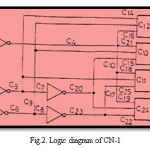
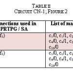
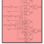
Using the above-mentioned procedures, we compiled the list of the masked faults for each circuit of our simulation study. Tables II shows one of such simulation results for circuit CN-1 (refer to manufacturer’s logical diagram as shown in Figure2).
It is noted that in a 3-bit LFSR, the number of those possible feedback connections which correspond to primitive polynomials is two, and they are (f0, f1, f3) and (f0, f2, f3). The feedback connections (f0, f1, f3) and (f0, f2, f3) are images of each other. It can be seen from the table that when the feedback connections of PRTSG and of SA are (f0, f1, f3) and (f0, f2, f3) respectively, which is image of each other,
then the identified masked faults are c1/0, c1/1, c2/0, c2/1, c3/0, c3/1, c4/0, c4/1, c5/0, c5/1, c6/0, c6/1, c26/0.
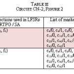
Further, it can also be observed from the results of the same table, that exactly the same faults are being masked when we use (f0, f2, f3) and (f0, f1, f3) as feedback connections in PRTSG and SA respectively. Also, another simulation result is presented here in Table III, which is obtained for CN-2 (see Figure 3).
In the interest of space, we presented the simulation results for only two circuits, but our findings are similar for other circuits of our simulation study as well. In addition, we simulated many more randomly selected circuits and observed the same results.
Conclusion
We have shown that when we use such linear maximal sequence generator in test pattern generation whose feedback connections are images of feedback connections of signature analyzer and corresponds to primitive characteristic polynomial then behaviors of faults masking remains identical. The results demonstrate that how the use of such feedback connections in pseudo-random test-sequence generator and signature analyzer yields to mask the same faults. These results are based on the simulation study of single stuck-at faults.
Thus, although maximal length pseudo-random binary-test sequences are the best ones for pseudo-exhaustive testing environment. However, this objective can only be achieved by proper selection of feedback connections of pseudo-random binary-test sequence generator as well as of signature analyzer. This identical fault mask behavior observed throughout this simulation study leads to the fact that the test schemes based on linear feedback shift registers need to be analyzed in totality instead of separately analyzing the LFSRs of either PRTSG or of SA to achieve higher fault coverage.
Acknowledgment
The authors would like to express their great appreciations and gratitude to Sultan Qaboos University, Sultanate of Oman for providing research facilities, technical supports and research environment.
References
- A. Ahmad, A. and A. H. Al-Habsi, A. H. “Design of a built-in multi-mode ICs tester with higher testability features- A most suitable testing tool for BIST environment”, Taylor & Francis online, pp. 283-288, 2015. http://www.tandfonline.com/loi/titr20
- A. Ahmad, D. Al-Abri, “Design of an optimal test simulator for Built-In Self-Test environment”. The Journal of Engineering Research.2010;7(2):69 – 79.
CrossRef
- A. Ahmad, A. and A. Al-Habsi, “Design of a built-in multi-mode ICs tester with higher testability features- A most suitable testing tool for BIST environment”. IETE Technical Review.1998;15(3):283 – 288.
CrossRef
- A. Ahmad, “Achievement of higher testability goals through the modification of shift register in LFSR based testing”. International Journal of Electronics.1997;82(3):249-260.
CrossRef
- N. K. Nanda, A. Ahmad and V. C. Gaindhar V.C., “Shift register modification for multipurpose use in combinational circuit testing”. International Journal of Electronics.1989;66(6):875 – 878.
CrossRef
- E. J. McCluskey, “Built-In Self-Test Techniques”. IEEE Design & Test of Computers.1985;2(2):21-28.
CrossRef
- A. Ahmad, A. and L. Hayat, “On design of 16-bit signature analyzer circuits equipped with primitive characteristic polynomials”, Proc. IEEE 1st Taibah University International Conference on Computing and Information Technology, ICCIT.2012;660 – 664.
CrossRef
- A. Ahmad, A., “On Design of 8-Bit CRC Circuits Equipped with Primitive Characteristic Polynomials”, Proc. IEEE International Conference on Multimedia, Signal Processing and Communication Technologies (IMPACT-2011);63 – 67.
- A. Ahmad, A. and L. Hayat, “Selection of Polynomials for Cyclic Redundancy Check for the use of High Speed Embedded – An Algorithmic Procedure”. Transactions on Computers (WSEAS).2011;10(1):16 – 20.
- A. Ahmad, A., “Investigation of Some Quite Interesting Divisibility Situations in a Signature Analyzer Implementation”. Transactions on Circuits and Systems (WSEAS).2011;10(9):299 – 308.
- A. Ahmad A., “Critical role of polynomial seeds on the effectiveness of an LFSR-based testing technique”. International Journal of Electronics.1994;77(2):127–137.
CrossRef
- A. Ahmad, A. and J. Al-Balushi, “How to Design an Effective Serial Input Shift Register (SISR) for Data Compression Process of Built-In Self-Test Methodology” Proc. IEEE 4th International Design and Test Workshop (IDT’09):372–379.
- A. Ahmad, “Constant error masking behavior of an internal XOR type signature analyzer due to the changed polynomial seeds.” Computers & Electrical Engineering.2002;28(6):577-585.
CrossRef
- A. Ahmad, A., “Investigation of a constant behavior aliasing errors in signature analysis due to the use of different ordered test-patterns in a BIST testing techniques”. Microelectronics and Reliability.2002;42:96 –974.
CrossRef
- T.W. Williams, W. Daehn, M. Gruetzner and C.W Starke, “Bounds and Analysis of Aliasing Errors in Linear Feedback Shift Registers”. IEEE Trans. Computer Aided-Design.1988;CAD-7(1):75-83.
- Ahmad A. and Nanda N.K., “Effectiveness of multiple compressions of multiple signatures”. International Journal of Electronics.1989;66(5):775–787.
CrossRef
- A. Ahmad, N. K. Nanda and K. Garg, “The use of irreducible characteristic polynomials in an LFSR based testing of digital circuits”, Proc. of 4th IEEE int’l conference (TENCON-89):494 – 496.
CrossRef
- J. P. Robinson and N. R. Saxena, “Simultaneous Signature and Syndrome Compression”. IEEE Trans. Computer Aided Design.1988CAD-7(5):589-594.
CrossRef
- S. Z. Hassan and E. J. Mc Cluskey, “Increased Fault-Coverage through Multiple Signatures”. Proc. 14th Int’l Symposium – Fault-Tolerant Computing (FTCS-14);1984:354-359.
- A. Ahmad and A. M. Elabdalla, “An efficient method to determine linear feedback connections in shift registers that generate maximal length pseudo-random up and down binary sequences”. Computer & Electrical Engineering.1997;23(1):33-39.
CrossRef
- A. Ahmad, N. K. Nanda and K. Garg, “Are primitive polynomials always best in signature analysis?” IEEE design & Test of Computers.1990;7(4):36–38.
CrossRef
- A. Ahmad, N. K. Nanda and K. Garg, “A critical role of primitive polynomials in an LFSR based testing technique”. IEE Electronics Letters.1988;24(15):953–955.
CrossRef

This work is licensed under a Creative Commons Attribution 4.0 International License.