Sangeeta Yadav¹, K. K. Pathak² and Rajesh Shrivastava³
¹Barkatullah University, Bhopal - 462 026 (India).
²Advanced Materials and Processes Research Institute (CSIR) Bhopal - 462 026 (India).
³Government Science & Commerce College Benazir, Bhopal - 462 003 (India).
Article Publishing History
Article Received on :
Article Accepted on :
Article Published :
Article Metrics
ABSTRACT:
In this study, shape optimisation of steel pedestals are attempted using neural network. Considering different geometrical parameters, finite element analyses of pedestals are carried out. Using these results, a back propagation neural network is trained. Successfully trained networks is further used for shape optimisation of newer problems. Thus optimised pedestals are further validated with finite element analyses counterparts and found to be in close match.
KEYWORDS:
Stress; Displacement; Finite Element; Pedestals; Neural Network
Copy the following to cite this article:
Yadav S, Pathak K. K, Shrivastava R. Shape Optimization of Pedestals Using Artificial Neural Network. Orient. J. Comp. Sci. and Technol;2(2)
|
Copy the following to cite this URL:
Yadav S, Pathak K. K, Shrivastava R. Shape Optimization of Pedestals Using Artificial Neural Network. Orient. J. Comp. Sci. and Technol;2(2). Available from: http://www.computerscijournal.org/?p=2138
|
Introduction
Th main objective of shape optimization is to find the shape which is optimal in the sense that it minimizes a certain objective function while satisfying the given constraints. Shape optimization is complex in the sense that the shapes are continuously changing during the optimization process. Careful consideration has to be paid to describe the changing boundary shape, to maintain an adequate finite element mesh.
Analytical methods for solving shape optimization problems have been used for a long time. The first known attempt at developing a mathematical formulation for shape optimization dates back to Galileo in 1638, who found that minimum weight cantilever is a parabolic beam. Use of numerical methods for shape optimization became main interest of scientists in this field after the invention of computers. In last 40 years a lot of progresses have been made in this field. Most of the shape optimization problems solved so far can be classified into gradientbased and gradientless methods. Both of these methods have their pros and cons and selection of a particular method depends upon the type and size of the problem, number of design variables and convergence required.
Durelli (1981) et al. adopted a step-by-step procedure for modifying hole boundaries in a two dimensional photoelastic model until the tensile and compressive boundary stresses were approximately constant. Mattheck (1990) based on the interesting observation that “living structures” appear to be able to add material in region of high stresses and to reduce material in region of low stresses, proposed methodoligies to bring about an optimal shape that produces a constant von Mises stress distribution on the free surface. Hasengawa, (1992) proposed two gradientless methods namely boundary changing methods, in which co-ordinates are changed, and thickness changing methods, in which thickness is changed. Jose (1990) and Sibal (1992) used this technique to find optimal shape of the downstream side of dams to eliminate tensile stress from the heel of the dams. In these problems co-ordinates of the nodes of the design points were varied in prescribed directions. Pathak (2000) used design elements, fuzzy set theory and artificial neural networks in a gradientless method of shape optimisation. Zhixue Wu (2005) presented an efficient gradientless shape optimization approach for minimizing stress concentration factor. Hsu (1993) developed a new method for optimization called as ‘curvature function method’. They solved various problems such as cantilever beam, fillet and torque arm. Ghoddosian (1998) extended curvature function method to find optimum shape of shell structures and successfully solved one circular and one spherical shell problems. The pattern transformation method of Oda and Yamazaki (1984) is a technique of transforming the shape of the boundary based on the stress ratio in the boundary finite elements. Umetani and Hirai (1979) used stress ratio approach whereas Tada and Seguchi (1981) considered strain energy ratios for shape optimization. Sehgal, et al. (1999) optimized bracket problem using Boundary Element Method (BEM) and zero-order approach. In recent years application of artificial intelligence based techniques have taken an important place in structural engineering and shape optimization is not untouched to that. Most important among them is evolutionary method, genetic algorithms (GA), neural networks etc. Nicholas Ali (2003) reported shape optimization of very large planer and space problems using GA. The proposed clubbing of FEA and GA finds lighter and reasonable structural design. Zhang(2005) reported application of meshless method and genetic algorithms for shape optimization of 2D problems. In this remeshing is avoided and particularly the computation burden and errors caused by sensitivity analysis are eliminated completely.
From the literature survey it is observed that shape optimization is one of the most complex problem which requires multidisciplinary knowledge like Numerical Mathematics; Finite Element Method (FEM); Computer Aided Design(CAD) etc. Since most of the design engineers are not well versed in these areas, shape optimization is still beyond their reach. To overcome this difficulty, to some extent, application of neural network is proposed in this study. The stress obtained from finite element analyses are used for training of neural network. Successfully trained network is used for prediction of optimal shapes. Several pedestals are designed using the approach and results are compared with finite element analysis results and both are found to be in good match.
Artificial neural network
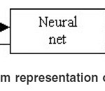
Artificial neural network attempts to imitate the learning activities of the brain. The human nervous system may be viewed as a three-stage system as depicted in the block diagram (Fig.1). Central to the system is the brain, represented by neural (nerve) net, which continually receives
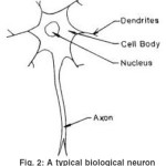
information, perceives it and make appropriate decisions. To sets of arrow are shown in the figure, those pointing from left to right indicate the forward transmission of information-bearing signals through the system. The arrows pointing from right to left signify the presence of feedback in the system.The receptors convert stimuli from the human body orexternal environment into electrical impulses that convey information to the neural net(brain). The effectors convert electrical impulses generated bythe neural net into discernible responses as system outputs. The human brain is composed of approximately 1011 neurons (nerve cells) of different types. In a typical neuron, we can find the nucleus, where the connections with other neurons are made through a network of fibers called dendrites. Extending out from the nucleus is the axon, which transmits , by means of a complex chemical process, electric potentials to the neurons with which the axon is connected to (Fig.2). When the signals received by the neuron equal or surpass their threshold, it “triggers”, sending the axon an electric signal of constant level and duration. In this way the message is transferred from one neuron to the other.
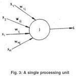
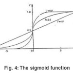
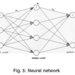
In an artificial neural network (ANN), the artificial neuron or the processing unit may have several input paths corresponding to the dendrites. The units combine usually, by a simple summation, the weighted values of these paths (Fig.3). The weighted value is passed to the neuron, where it is modified by threshold function such as sigmoid function (Fig.4). The modified value is directly presented to the next neuron. In Fig.5 a 3-4-2 feed forward back propagation artificial neural network is shown. The connections between various neurons are strengthened or weakened
according to the experiences obtained during the training. The algorithm for training the back propagation neural network can be explained in the following steps-
Step 1
Select the number of hidden layers, number of iterations, tolerance of the mean square error and initialize the weights and bias functions.
Step 2
Present the normalized input –output pattern sets to the network. At each node of the network except the nodes on input layer, calculate the weighted sum of the inputs, add bias and apply sigmoid function
Step 3
Calculate total mean error . If error is less than permissible limit, the training process is stopped. Otherwise,
Step4
Change the weights and bias values based on generalized delta rule and repeat step 2.
The mathematical formulations of training the network can be found in Ref.4.
Methodology
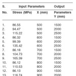
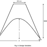
A pedestal of height 3000mm and and width of top and bottom surface 300mm and 500mm is shown in Fig.6. Let P be the concentrated load at the top surface of the pedestal. Thickness of the pedestal is 150mm. Let X and Y be the width and depth of the pedestal respectively. Various combinations of these geometrical parameters are framed and analysed using FEM. Results for these cases are recorded in terms of peak bending stress. These data are used for training of the neural network. Successfully trained network is employed for shape optimisation of newer problems.
Finite Element Analysis
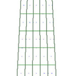
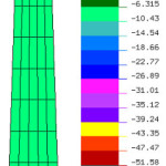
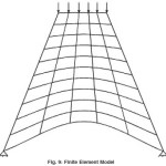
In this study a pedestal of width at top and bottom surface as 300 mm and 500 mm and depth 3000 mm is considered. Various combinations of X and Y are accounted. Considering these variations in geometrical parameters, 13 cases are framed (Table 1). Nine noded Lagrangian element is used for Finite Element modelling .The pedestal is divided into 50 elements making up 231 nodes (Fig.2). An automatic mesh generator has been developed to generate finite element mesh for these cases. Young’s Modulus of 2×10 5 MPa and Poisson’s ratio 0.3 is accounted. The stress contour is shown in Fig. 7. The design variables are shown in Fig. 8 and Fig. 9 respectively. Considering these data, linear elastic finite element analyses of the 13 cases are carried out and maximum value of bending stresses is noted for each case (Table 1). The finite element analysis results are given in Table 1.
Application of Neural Network
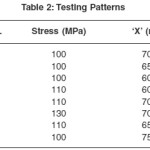
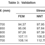
Stresses obtained from finite element analyses, are used for training the neural network. For this a 2-3-1 size, back propagation neural network is adopted. The input parameters are stress and ‘X’ and output parameter ís ‘Y’.It took 543268 epochs to converge to an error tolerance limit of 0.01. The trained network is used for predicting geometrical parameters for new testing patterns given in Table 2. To validate the neural network predictions finite element analyses considering these data is carried out. The stress obtained from FEA and corresponding percentage error are given in Table 3. Maximum error in stress is 4.26 which is quite acceptable. This may be acceptable at first hand design. Based on the requirement, it may be further improved using more rigorous approaches.
Conclusion
In this study, an application of neural network is demonstrated on shape optimization problems of pedestals. It overcomes some of the drawbacks of conventional approaches of shape optimisation, like high computational time and large memory requirement. It is observed that proposed approach works efficiently for optimizing shape accounting stress criteria. It offers a handy tool for design engineers who are not familiar with the theoretical and computational aspects of shape optimization.
References
- Durelli A., Optimum shape of central holes in square plates subjected to uniaxial uniform load, Int. J. Solid and Struct., 17: 787-793 (1981).
- Ghoddosian, A., Improved Zero Order Techniques for Structural Shape Optimization using FEM, Ph.D Dissertation, Applied Mechanics Dept. IIT Delhi (1998).
- Hasengawa, A., Shape optimization of two dimensional bodies by boundary changing method and thickness changing method, Int. J. Num. Met. Engg., 34: 889-892(1992).
- Hertz J. and Krogh, A., Introduction to the Theory of Neural Networks, Addison- Wesley Publishing Company, (1991).
- Hsu, Y.L., Sheppard, S.D and Wilde, D.J., The curvature function method for two-dimensional shape optimization under stress constraints, Int. J. Comp. & Struct., 55: 647-657(1993).
- Jose. P.C., Strengthening and Optimisation of Gravity Dams, Ph.D Dissertation, Applied Mechanics Dept. IIT Delhi, (1990).
- Mattheck, C., A new method of structural shape optimization based on biological growth.,Int. J. Fatigue,12: 185-190(1990).
- Mattheck,C., Three dimensional shape optimization of a bar with a rectangular hole, Fatigue Fracture Engg. Mater. Structs,15:347-351(1992).
- Nicholas Ali, Applicability and viability of a GA based finite element architecture for structural design optimization, Comp. & Struct.,81: 2259-2271(2003).
- Oda, J. and Yamazaki, K., Pattern transformation method for shape optimization and its applications to spooked rotary disks, Int. Sym. On Optim. Stuct. Des., University of Arizona, Tucson, AZ., 429-435(1984).
- Pathak, K.K., Gradientless Shape Optimisation of Concrete Structures using Artificial Neural Networks, Ph.D Thesis, Applied Mechanics Dept. IIT Delhi (2001).
- Sehgal, D.K., A.K Srivastava A.K and Pathak K.K, Shape Optimization of an automotive bracket, 11th ISME Conf., IIT Delhi, Feb. 3-5, (1999).
- Sibal , S.K., Optimal Shape Design of Concrete Gravity Dams, M.Tech. Thesis, Applied Mechanics Dept. IIT Delhi,(1992).
- Tada, Y., and Seguchi, Y., Shape optimization of structures based on inverse variational principle, the finite element approach, Int. Sym on Optim. Sruct. Des., University of Arizona, Tucson, AZ., (1981).
- Umetani, Y. and Hirai, S., Shape optimization of beams subject to displacement restrictions on the basis of the growing-reforming procedure, Bull, JSME, 21: 1113-1119 (1979).
- Zhang A.Q., Zhou J.X., Zhou N., Wang X.M and Zhang L., Shape optimisation using reproducing kernel particle method and an enriched genetic algorithm, Comp. Meth. in App. Mech. and Engg.,194: 3817-3837(2005).
- Zhixue Wu; An efficient approach for shape optimization of components, Int. J. of Mech. Sci.,47: 1595-1610 (2005).

This work is licensed under a Creative Commons Attribution 4.0 International License.