Introduction
The Transport Management System (TMS) has developed integrated GPS/GIS for collecting on-road traffic data from a probe vehicle. This system has been further integrated with the engine management system of a vehicle to provide time-tagged data on GPS position and speed, distance travelled, acceleration, fuel consumption, engine performance, and air pollutant emissions on a second-by-second basis.
All GPS/GIS tracking systems use the Global Positioning System to determine and regularly record the location of an object and it can be used to calculate the targeted objects speed. The systems are popular with government and law enforcement officials, and have many civilian applications. Transportation data, in common with many other data sets in civil engineering and the social sciences, often have spatial attributes. For example, traffic counts come from specific sites, travel time data refer to particular routes, and origin–destination data apply to a given area.[23] Generally, these fall into the following areas: tracking, mapping, navigating, locating and obtaining precise timing [8].
GPS works anywhere in the world and the information is available 24 hours a day. Luckily the government does not impose subscription fees to use the system. [9]
A key element of the TMS is the use of GPS data to determine locations, for both static observations and dynamic recording of vehicle positions over time. The GIS takes on the central role in data management, in terms of data entry and integration, data management, and some aspects of data analysis and display. [23]
The GPS is a network of satellites placed into orbit by the U.S. Department of Defense. There are 24 satellites available in space and it is guaranteed that at any given time, there will be at least three satellites available anywhere under the sky. [8] But now many countries like European union and Japan are doing similar project of their own system. Receivers can catch the signals at least from these three satellites to guarantee the accuracy of signals caught from them. GSM (Global System for Mobile communications) technology is used to transmit this and display the geographical position of the vehicle at the base station, [13] and special sensitive cameras distributed at the road sides.
The integration of GIS-GPS technologies can be achieved in many ways. GIS-GPS integration has numerous applications in various fields [1,3].
One of them is vehicle tracking, which is one of the most developing field, by vehicle tracking in addition we mean vehicle speed check too [8]. In this paper, we would like to present the TMS depending on vehicle tracking and speed check system for vehicle (object) navigation, which is depends on online mode.
GIS and GPS technology have brought some breakthrough in the area of transportation monitoring and management. One of the most useful applications is a vehicle tracking system to determine and trace the position of the mobile vehicle [1] and to avoid road congestions. The system locates vehicles using GPS satellites, GPS receivers and other auxiliary equipments display the geographical coordinate of the vehicle position on a digital road map of the monitoring system [10].
Conventional database systems cannot make much use of the spatial or locational attributes of a data set, other than hold reference details for it. Geographical Information Systems (GIS), on the other hand, can absorb a database, relate its spatial attributes to maps of the region, and offer spatial integration with other pertinent databases for that region.[23]
The digital map is a vector-typed spatial database to manage topologically the spatial objects which correspond to entities existing in the real world. The map used in the vehicle tracking system contains a variety of geographic and traffic-oriented resources and rules; and keeps the up-to-date information on roads like the speed limits, buildings, traffic signals, road constructions and associated transportation facilities. In case of a distributed environment which each monitoring station needs to possess its own spatial database, essential to the entire system, is to guarantee data integrity or data consistency among all the database holders [7].
This paper describes the design and implementation of the client/server solution for spatial data processing crucial to measure the speed of a mobile vehicle and tracking its position. And offers alternative text coordinates of a spatial database. A data caching technique is introduced in order to enhance the transmission efficiency between both sides. Also, technical issues of GPS, DGPS (Differential GPS) and wireless communication fields are presented to reach the proposed goal [11,14].
Some systems can pinpoint location within less than 2 meters. A GPS receiver needs information from at least two satellites to calculate a 2-D position (latitude and longitude), but with four or more satellites, a 3-D picture (latitude, longitude, and altitude) can be obtained. After that, speed, bearing, distance to a destination and other information may be calculated. With special software, an animated picture may be imposed over a street map or satellite image or displayed in a report format.
Spatial Data Processing Methodology
Spatial data processing based on a client/server structure may be a methodology well-suited for tackling this burdening problem. The approach employs a server and multi-clients architecture in which the server exists in a control center and each client falls under one of monitoring stations [5,15]. available in any public transportation agents or private companies or Traffic Control Police Station. The proposed structure may achieve the data integrity and cost-effective maintenance of database, since the server manages exclusively the spatial data and deals with a series of processes requested from the client side. One of the big advantages is that if the server and clients are connected on-line, the server would obtain the traffic information occurring on the streets, the base station obtains the traffic information from the clients in text format corresponding the spatial data which stored in spatial database, the clients benefits those without any interconnection to other information channels.
GIS-GPS Integration
The integration of the various data collection modules in the vehicle is a major task facilitated by the use of GIS. The data collection modules include differential GPS (for time-based location, speed, and direction of travel), and on-board vehicle data like speed, acceleration, fuel consumption, engine performance, and emission rates. [1] The GIS system makes strong use of GPS for real-time data collection, and integration with a radio communications system allows for the real-time tracking of a fleet of probe vehicles, as well as post-processing of the on-road data. [23]
The integration of GPS technology into GIS activities can be achieved through a variety of means. These range from the transfer of data from GPS systems, for the building of new Spatial database, to the complete integration of GPS technology into existing GIS systems, to conduct spatial analysis directly in the field [6]. The GIS-GPS integration can be done in three categories: Data-focused integration, Position-focused integration, Technology-focused integration. The appropriateness of each method is dependent upon the requirements that a user has for field-based operations, the level of dependence the user has on GPS and, to a large extent, the availability of a complete system to meet the specific needs that the user has for a system.
What Does it Do?
A GPS receiver accepts the signals involving the satellite’s clock and orbit information of each one of the seen satellites and calculates the difference between the receiver clock at the signal’s reception time and the satellite clock at its transmission time. The time difference derives a distance from the receiver to each one of satellites and then the location of each satellite can be elicited from its orbit information. Finally, the location of the receiver is computed. As you see in the overview of vehicle tracking system illustrated in Figure 1. The signal travels to the ground at the speed of light. Even at this speed, the signal takes a measurable amount of time to reach the receiver. The difference between the time when the signal is received and the time when it was sent, multiplied by the speed of light, enables the receiver to calculate the distance to the satellite. D = t1-t2 *LS where LS is Light Speed, and d is distance of the satellite, and t1,t2 are time of Transmition and the time of receiving the signals. To make this measurement as accurate as possible, the GPS navigation signals are specially designed to make it easy for GPS receivers to measure the time of arrival and to allow all the satellites to operate on the same frequency without interfering with each other. To calculate its precise latitude, longitude, and altitude, the receiver measures the distance to four separate GPS satellites. By using four satellites, the receiver calculates both its position and the time and doesn’t need an expensive atomic clock like those on the satellites.
A GPS receiver monitors microwave signals from the orbiting satellites. These signals contain the time of transmission and the position of the satellite, and these signals are corresponding to the signals caught from the receiver of the mobile vehicle by the satellite, and each signal is known from which receiver is delivered and it reflects the signals come from the vehicles. The receiver analyzes these signals by using the travel time of the signals and positions of the transmitting satellites to trilateral position. At least two signals are necessary to find the position, and four signals are necessary for a definite position using the GPS system.
In an automotive-based GPS system, this GPS coordinate data is fed into the unit’s database of road information, indicating your location on a stored map. This database and location information is also usually analyzed to provide directions to a given destination.
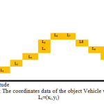
While the object is traveling from point to point, its coordinates are changing through time, and the system can register these coordinates, and use it to monitor the object. L1=(x1, y1) the first position of the vehicle, L2= (x2, y2) the Second position of the vehicle,… Ln= (xn, yn) the n position of the vehicle. D1= L2- L1 where D1 is the first distance the vehicle mileage. D2=A3-A2 where D2 is the second distance the vehicle mileage, Dn= Ln– Ln-1 where Dn is the n distance the vehicle mileage. The time period between sending two signals to the vehicle receiver from the first and second satellite is t1=S1t2- S1t1 from the first and t2=S2t2- S2t1 from the second. The speed in period between any two signals from the first satellite is S1 = D1/t1, and the in period between any two signals from the second satellite is S2 = D2/t2, the average speed of the object in a known period time according the first satellite is equal to:
s1 = ΣDs1 / Σts1 where Ds1 is the distance mileage according the first satellite, and ts1 is the period of time taken by the object for undertaken mileage.
The average speed of the object in a given time according to the second satellite is equal to:
s2 = ΣDs2 / Σts2 where Ds2 is the distance mileage according the second satellite, and ts2 is the period of time taken by the object for undertaken mileage.
The average speed of the mobile object in a known period of time according to the first and second satellites is equal to:
s = s1 + s2/ 2 This simply if we receive the signals only from two satellites, and we can do the same by the other signal to calculate the speed more accurate, and you can note that minimal period of time between signals is better and more accurate to calculate the speed of an object.
Features of TMS
We can take in our consideration many additional features to help the system users and to fulfill their needs, some of these features are as the following:
- Messages received from the Central station can be displayed on cellular phones, or on an LCD at the road side.
- The drivers can send messages to querying traffic situation and congestions from the station.
- Alarm information can be transmitted to the central base station instantly.
- Automatic registration of speed traffic violation.
- Automatic registration of locations the vehicle crossed over.
Base Station of VSC and VTS
The Base Station includes a GSM Module and Web Server that allows the controller to view the vehicle on a Geographic map. Multi layer in-depth maps of each city are available and the position of VTS of the vehicle is displayed on these maps. The Base Station has an in-built Web Server. The position (VTS) information received from each vehicle is stored in the database. And according to its location the system calculates the current speed and registers it in database simultaneously of the Commission traffic control in the base station according to the vehicle ID which is saved in the vehicle receiver and it is transmits with signals. The system transmitted a message to the vehicle if its speed exceeded the limits fixed for that location.
Spatial Data Processing Structure
Spatial data are a collection of graphic data [7,16]. Now we can consider two techniques to handle such spatial data appropriately; one is to use an existing DBMS (Database Management System) as the underlying storage and to introduce a distinct engine which is intended for spatial processes. The other is to adopt a specially-designed DBMS to process both spatial and non-spatial data concurrently [2,15]. Even if the latter is a recommendable approach to view both data in a unified data type or object by devising a new data model, it must be a challenging task in that design and implementation of the system demands substantial amount of time and extensive research efforts. On the other hand, the first one has its merit in that it facilitates system’s implementation, reuses powerful utilities and functions such as concurrency control, recovery, and transaction management available in the conventional DBMS [2].
Simply the system is based on ordinary DB that simulates the spatial DB in work its function but it also based on text and numbers which reflects or corresponds to the location coordinates of the objects alternative to the spatial DB to decrease the data size and slow processing. The coordinates stored in DB are based on the exactly GPS given coordinates for the object locations like streets in our case and other objects on it, the two databases are completely linked and corresponds each another.
The suggested system adopts intensive link between first DB in which stored spatial objects, and the corresponding database stored textual data coordinates objects. The synchronic connection between these databases and the server in the land base station is available to fix the location of the object at any segment of time, and calculates the object location and speed and records the data that violates the norms or limits in that location (exceeded the limits of speed) objects using special algorithm.
The input/output manager can manipulate the multi-connections at one time and create a unique process for each client.
System Wireless Communication
As you notice, the vehicle tracking system needs to be channeled or directed by a wireless communication link from the receiver of the vehicle to the monitoring station. Beyond this kind of immediate demand, the advent of wireless era accelerates the nationwide construction of various wireless networks. Currently, a conventional private network, a TRS (Trunked Radio System) network, a cellular network, a satellite network and a data packet network may be a candidate for the application.
Now, let us briefly examine the characteristics of each one. A private network enables user to utilize its unique radio-frequency, but it restricts severely the number of vehicles to be monitored because its circuit switching prevents other users from accessing the primitive line. TRS gives a wide range of frequencies which a large number of users can share. Users enjoy a high rate of connections, a good quality of voice data and more a reasonable cost of communication. Recently, researches on digital TRS are actively under way in order to overcome some restraints of the analogue method. A satellite network has a extensive coverage for the service. Its disadvantage is, however, a low rate of data transmission in addition to expensive receiver equipments.
A data packet network is considered applicable in that a message is transmitted by a series of short packets and its packet switching sequentially increases the network utilization. Besides, it makes retransmission of lost data possible when an error happens during the transmission. Actually, in case of the vehicle monitoring which data transmissions are frequently occurring in a short term, the data packet may be a effective means of communication. In the data packet network, the messages are exchanged between the receiver and the station through a wireless modem connected to the receiver. A unique identification number assigned to each modem tells the location of a specific vehicle that carries it.
TMS Configuration
The TMS is completely modular in design. It is made up of three main parts including the satellite as one of them: The Mobile Vehicle Unit (receiver) and The Fixed Base Station or monitoring station (receiver and controller). And it includes next listed units:
- GPS Module
- GSM Module
- Controller Module
- Storage module (optional)
- Display/Entry module
- Additional Sensing modules (temperature, accident, speed, etc.)
The TMS unit is configured around main Controller module, which executes the software to configure and control the GPS receiver, GSM module, and (optional) IO Ports. This unit is to be fixed in the vehicle, with appropriate GPS and wireless antenna.
The GPS receiver detects the position and provides it to the Controller module. The
Controller module converts the received data and sends it to the central station using SMS or another media to the spatial database [19].
As mentioned earlier, the server system is composed of relational DBMS, Oracle and GIS engine, SDE installed on the top of UNIX operating system. Each client system available in the monitoring stations keeps a copy of the application program which is designed and developed with SDE’s API, ODBC (Open Data Base Connectivity). There is an integrator module located between the two databases to coordinate their contents and to response the controller. The future application program for the TMS will consists of four main software modules.
- Map Control.
- Information Management.
- Vehicle Operation Control.
- Message Management.
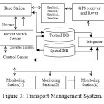
The components to form the TMS are illustrated in Figure 3. As you see, each vehicle transmits GPS data related to its location through network which is hierarchically made up of base-stations, local switches, and a packet switch center. The control center hands over the data from the packet switch center to a corresponding monitoring station via a dedicated line. On the other hand, the DGPS base station dispenses the information indispensable to the database in the base station. For correcting the inaccurate location of vehicles, following the reverse order of paths shown in the packet network [2,21]. Here, another dedicated line needs to be installed between the DGPS station and the packet switch center. Finally, vehicles send back the current location to the monitoring station.
Database Integrator
In the suggested client/server structure, an intensive control center plays an active role, to settle the inconsistent data and consequential maintenance resulting from the situation in which the regional dispersed monitoring stations share the same spatial data for their own purpose of transport management. The spatial DB server is to keep the periodically updated road map that basically sends the data by peculiar units of layers according to request of clients. The client systems of public agencies/institutions or private enterprises closely related with the transportation affairs utilize those data immediately transferred into main-memory in the powerful PC-based system [5,20,22].
We apply a spatial data caching (integrator) technique to the client/server system in order to decrease the time period of transmission and the size of data downloaded, and eventually to raise the system efficiency. At initial booting time of the client system, a main part of monitoring areas may be activated through cache memory or cache disk, and then those cached areas are brought up instantly at the speed of memory access without giving any burden to the server. Whenever a request for other areas and layers is made, the server replies by following the usual procedures and sends the corresponding data. Empirically, the desirable size of cache is about twice as much as the main-memory of the monitoring system. First of all, selection of the layers which are necessarily entailed with the spatial area to be cached must be taken into consideration. The fundamental layers for the road map contain numerous geographical themes; roads, railroads, streams, rivers, administrative districts, transportation, buildings and many more. The number of layers entirely decides the level of spatial data processing in the vehicle tracking system.
Implementation
To conduct an experiment for the TMS, we choose part of a highway as a sample, to simplify the spatial database. The main center and the monitoring stations build up the client/server structure through the dedicated lines of high speed. Normally, the coordinate system to represent the position by GPS is WGS-84 which is not suitable for display on the plane map. We, therefore, develop a program to convert it into TM coordinate in order to achieve successful mapping. The information as to a vehicle’s location is kept in a log file which usually contains an ID number of the vehicle, receiving time of GPS’s location data, the converted TM coordinate, direction of the vehicle and so on. Later, we can keep track of the history of paths from this log data. In addition to the location data, the client program facilitates exchange of the messages associated with an intended service by using function keys in the receiver.
The digital map includes center lines within the roads to take advantage of a map-matching technique applied to the car navigation frequently. Based on the condition that “the land vehicle is almost always running on the roads”, map-matching is a mechanism to hold the positioning accuracy even in cases that the vehicle experiences some difficulties in receiving the signals, or seems to be run out due to the error of the digital map. Separately from center lines, nodes point to intersections are involved in the map data [7]. The information of center lines and nodes offer a way to find out the shortest path from origin to destination. And some other information we use to calculate congestion, We incorporate into the client program, a sophisticated algorithm to discover a geometrically shortest path.
Conclusion
In this paper, core issues have been described regarding GIS, GPS and wireless communication networks to be evolved during the development of the land TMS. The implemented method has been also presented with client/server solution in textual road coordinates database and spatial data processing, and a data-caching (data-Integrator) technique which is suitable for data retrievals in reasonable response time.
The land TMS is an application programs that we can develop to construct the national logistics network. As a result of implementing a prototype system, the data integrity and the cost-effective maintenance of spatial database and textual road coordinates database can be fulfilled.
A Nationwide service of the system requires the application of more advanced technology such as satellite communication or multi-DGPS, and full spatial database and textual road coordinates database. There are yet more to study: how many vehicles a control center can handle and process simultaneously, how often the vehicles can be polled to get their locations at the right moment.
References
- S.Kiruthivasan, C.Madan Deepakumar, Decision Support System For Call Taxi Navigation Using GIS-GPS Integratio, Charles Vlcek, Patricia Mclain, and Michael Murphy, “GPS/Dead Reckoning for Vehicle Tracking in the Urban Canyon Environment”, Trimble Navigation, Ltd., 1993.
- D. J. Maguire, “An Overview and Definition of GIS”, Geographical Information Systems, Vol. 1, pp. 9-20, 1992
- Michael Goodchild, “Accuracy of Spatial Databases”, Tayler Francis, 1989
- O. Guenther and A. Buchmann, “Research Issues In Spatial Databases”, SIGMOD RECORD, Vol. 19, No. 4, pp. 61-68, 1990.
CrossRef
- R. H. Guting, “An Introduction to Spatial Database Systems”, VLDB Journal, Vol. 3, No. 4, pp. 357-399, 1994.
CrossRef
- Robert L. French, “Land Vehicle Navigation and Tracking”, Global Positioning System : Theory and Applications, Vol. 164, pp. 275-301, 1996
- Ronald Braff, “Applications of the GPS to Air Traffic Control”, Global Positioning System : Theory and Applications, Vol. 164, pp. 327-374, 1996
- Steven E. Shladover, “Research and Development Needs for Advanced Vehicle Control Systems”, IEEE Computer Society, 1993.
- W. Richard Stevens, UNIX Network Programming, Prentice-Hall International, Inc., pp. 258-277, 1994
- ESRI, Introduction to SDE, 1995
- Jim Sennott, “Marine Applications”, Global Positioning System : Theory and Applications, Vol. 164, pp. 303-325, 1996
- 2005B. C. Ooi and K. J. McDonell, “Extending a DBMS For Geographic Applications”, Proc. of IEEE Data Engineering, pp. 590-597, 1989.
CrossRef
- 27sep2010 http://www.gisdevelopment.net/tutorials/tuman004.htm
- 27sep2010
- http://hyperphysics.phy-astr.gsu.edu/Hbase/gpsrec.html
- 27sep2010 http://www.quentind.com/quantum/global_positioning_system.htm
- 27sep2010 http://msl.jpl.nasa.gov/Programs/gps.html
- 27sep2010 http://www.aero.org/education/primers/gps
- 27sep2010 http://www.nasm.si.edu/exhibitions/gps/work.html
- 27sep2010 http://electronics.howstuffworks.com/gadgets/travel/gps.htm
- 27sep2010 http://www.trimble.com/gps/index.shtml
- 27sep2010 http://searchmobilecomputing.techtarget.com/definition/Global-Positioning-System
- Michael A.P, Taylor, E. Woolley, Rocco Zito, integration of GPS and GIS for traffic congestion studies, University of South Australia, sep. 2000

This work is licensed under a Creative Commons Attribution 4.0 International License.