Introduction
A “mobile adhoc network” (MANET) is an autonomous system of mobile routers (and associated hosts) connected by wireless links, the union of which forms an arbitrary graph. The routers are free to move randomly and organize themselves arbitrarily; thus, the network’s wireless topology may change rapidly and unpredictably. Such a network may operate in a standalone fashion, or may be connected to the larger Internet. Because, adhoc networks, from a routing perspective, can be seen as a multi-hop network with mobile nodes and hence constantly changing routes. With a constantly changing topology it becomes essential to have a distributed algorithm, which incurs the least communication overhead [1]. In case of emergency, the topography is different in the amount of obstacles that may arise due to the occurrence of a undesired events causing the normal mobility pathways to alter. Therefore, the algorithm of motion is determined according to the topography, and the corresponding nodes must be moved depending on the obstacles. The number of nodes depends on the environment of MANET network if it is an urban or in a rural area. When an unwanted event has occurred, MANET changes the pathways of normal mobility. Therefore new routes for evacuation and rescue should be calculated. It is of vital importance for rescue personnel to obtain an accurate and consistent picture of the situation, and to regain control and coordination on the shortest possible notice. This situation prevents further escalation, minimizes the number of casualties and restricts the damage [2]. The current communication systems are very traditional for rescue services. They suffer from high vulnerability due to the fact that they rely on a fixed infrastructure and lack of self-organization capabilities, do not support multimedia applications asking for high quality communications and/or high bandwidth [4].
The rest of the paper is organized as follows. In Section 2, a proposed watermarking algorithm is presented .Experimental results are shown in Section 3. Conclusions and suggestion for future works are drawn in Section 4.
The proposed system
The proposed system presents analytic study for constructing proposed medical emergency systems to achieve life rescue in time and place. It consists of two schemes
Scheme 1: Deterministic Information Source Location (DISL)
This scheme serves the emergency request depend on determinate the source of the request location in order to determine the request zone and draw the rout path for it. This scheme depends on the source node and the surrounded nodes, whether they are neighbours with the same direction or not. DISL must be fully distributed, such that the node that detects an emergency message need only broadcast the message to other nodes in a short range. The scheme must be able to provide multi level of priority scheduling for emergency packets and determining message level to put it in the packet header with a number of duplicate copies to send for each message.
Scheme2: an Antenna Usage
The implementation of this scheme can be listed in two methods:
Method 1
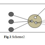
This method requires essential components which are control point, an antenna and small mobile units or worn by users. This methods should be coexist and provide access to public and other emergency network systems. The control point may be vehicles or permanent points with known address provided with an antenna. The control point detects an emergency event as soon as possible and delivered its emergency messages to each node nearby with almost no delays. The method should be deployed easily and quickly with little human maintenance. In this method, the devices must be capable of configuring themselves into a network. The Procedures that involved is self-organization are include ad-hoc network creation, ad-hoc device discovery, connection establishment, scheduling, address allocation, routing and topology management. This method consists of two ad-hoc networks:
This first layer assigned for communication between end points (rescue workers, devices). The second layer is acting as communication backbone (control point) between clusters of endpoint and gateway nodes to external networks.
The method contains personal nodes, control point nodes and gateway as illustrated in Fig.1.
piggybacking the location information on other packets in addition to route replies. Also, to get a smaller request zone at speeds that are neither too small, nor too large.
To define the shape region, one side of the shape made parallel to the line connecting the location of node S to previous location of D. This approach would often result in a smaller request zone.
Determination the size of the request zone for scheme 1
This determination concluded in the following:
1- Accuracy of a request zone Z (finding a route to the destination) which is determined by the source node S, with up-to-date location information for host D at time t1, that is based on location information about D learned by S at time t0.
The personal nodes provide networking facilities to persons. The control nodes are installed in an ad hoc vehicle or at known addresses permanents point. A gateway is a control node with capability of providing interfaces to other types of networks.
Method 2
In this method, the antenna is installed in each ad hoc node in a directional way.
The Rout Algorithm
The rout algorithm and location discovery of scheme 1 and scheme 2 requires:
Determination the size of the request zone
the size of the request zone is proportional to (i) average speed of movement v, and (ii) time elapsed since the last known location of the destination was recorded.
The proportional of factor (i) and (ii) is:
if (i) became small, factor (ii) becomes large at low speeds, potentially resulting in a larger request zone. It is possible to reduce the size of the request zone in low speed by 2-The route request includes the time stamp t0, because the location of node D at time t0 is used to determine the request zone, location of node S and the time t1 when the request is originated are also included.
3- Intermediate node I within Z receives the route request at time t2, where t1 < t2.
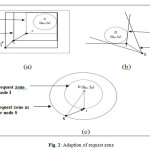
Request zone initially determined at a source node adapted at node I. Node I may determine the expected zone using more recent location information for node D, and define the adapted request zone containing node S and the new expected zone for node D. The request zone for the request propagated by node I includes the current location of I and the expected zone of the destination D. Fig. 2(a) illustrates the above procedure. From the Fig. 2(a), a node I receive the route request from the source S and forwards the request to its neighbours, because I is within the request zone Z (defined by S), it can replace Z by an adapted request zone Z’ before forwarding the request. The same procedure is done with node J that receives the request message from node I and the request zone can be adapted again.
In general, the shape of the request zone can be constructed in any form. For instance, Fig. 2(b) shows the case when the request zone is defined as a cone rooted at node S, such that angle made by the cone is large enough to include the request zone. The angle made by the cone may be chosen by some other heuristic as well (for instance, if the angle is always chosen to be 90 degrees, this scheme would become similar to that in Fig. 2(a)). Similar to adaptation of the rectangular request zone in Fig. 2(a), the cone-shaped request zone may also be adapted as shown in Fig. 2(c).
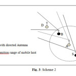
From Fig. 1 and 3, the node S having a directional antenna initiates a route discovery phase for node D. Based on the previous location information of D, a route request packets may be directed only for a small group of mobile nodes (Fig. 3). Therefore, a node C does not receive the request packet from S even though C is a neighbor of S. When node A forwards the route request (originated by node S), it applies a similar criteria, and so on until reaching a node D.
Determination the size of the request zone for scheme 2
This scheme based on using a directed antenna with control point (vehicle, permanent points), or by selecting nodes to define the request zone. The routing algorithm for this scheme is illustrated as follows
- The request is initiated with node S to node D via antenna and location information of D. This request is directed to a small no. of nodes.
- The intermediate nodes forward the request to the next node, If it is within the range of rout packets, else The neighbours will not receive the rout request if isn’t mentioned in the rout packets, even if they are under the cover area of S
- By continuing this fashion, the request zone determinate in a little cost of net routing. Fig. 1 and 3 illustrate the above procedure.
expanded to the entire network space gradually, to avoid performance degradation. With the assumption that only average speed of the nodes is known with additional information may be available (like, direction of movement).
Location Discovery
The location discovery is done by letting all the nodes receive the request and having each of them retransmit it again. In order to achieve the goal of location discovery, there is no need for all nodes to transmit/retransmit the message. Instead, only few strategically selected nodes retransmit the message by select the nearest node to the point selected, to retransmit the message. To receive the message, we select the mobile node (MN) that has received the message and is also the nearest to the selected point. The algorithm location discovery is described below
- At Source Node S:
S chooses MNs in its range R, which form the best approximation of a request zone and transmits their identities along with the request.
2. At an Intermediate MN
A Mobile Node upon receiving a request first determines if it is intended that the request be retransmitted by it. Then, if it has to retransmit the message, it checks if it has received the request directly from S.
If yes, then it calculates the next node to broadcast the request. Let Ps be the location of S, Pi the location intermediate node and Pn the location of next node. Then next node, here, is the node which is nearest to Pn given by Pn = 2*Pi – Ps (as Pi bisects the line joining Pn and Ps). Then, the MN appends the location of Pn to the request and broadcasts the request.
else If the request wasn’t received directly from the source S, then, the MN using the location of the other MNs in its range finds the MN(s), which is (are) nearest to the location(s) calculated and appends the MN identifier(s) to the request. Then it re-transmits the request.
The MN doesn’t re-transmit the request if the following two conditions hold true:
if no nodes are present in the range of the MN except for the MN from which the request was received or if (all) the location(s) of the next node(s) that have to re-broad cast the request are out of the region to be covered.
Experimental results
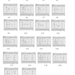
In this paper a medical emergency system of Mergan Hospital in Al_Hilla city (in Iraq) is simulated by using NS2 simulator. The infrastructure of the system consist of four parties (patient, control point, ambulance, and emergency department). Nodes (0,1, 2) represent the patient request for ambulance. Node (3) represents the control point. Nodes (4, 5, 6) represent the ambulance movement. Nodes (7, 8, 9) emergency department. The scenario can begin from any patient (0,1,2,…) request to the central point (vehicle, permanent points) or selected nodes for an ambulance. The control point or selected nodes in turn broadcast the message for a nearest emergency department for an ambulance as soon as possible to replay to the patient again. Consequently, the emergency department retransmit the message to all the ambulance cars if they available behind the department or not. Fig. 4 describes the replay message from the ambulance nodes (4, 5, 6) to the requests of patient (0, 1, 2) through node(3) which supplied by an antenna, this node for method 1, may be a vehicle or permanent points, or selected nodes in an ad hoc net for method 2. With a selected area of (900* 3000 m).
Conclusion and future work
In this paper an analytic study to enhance the quality of service and support autonomous operation in emergency cases is presented. Two studies for constructing emergency networking system using ad hoc net are presented. The first one depend s on using deterministic information source location (DISL) methods, where the source of the request location and the surrounded nodes if they are neighbors with the same direction or not are used to determine the request zone and draw the rout path for the destination node. This study limits the search for a route to the so-called request zone, the determination based on the expected location of the destination node at the time of route discovery. In our implementation, the sender comes to know location of the destination only at the end of route discovery. Although, the location information used to reduce the routing overhead in ad hoc network, the scheme does not require a periodic broadcast of location information, unlike [3].
The second study used the antenna with each node in the net in a directional way. The simulation has proved that the second one is better than the first, because the first implies that any request message broadcast by a node will reach all its neighbors, even if some of these neighbors are outside the intended request zone, i.e., there is a large overhead routing. Simulation results indicate that using location information results in significantly lower routing overhead, as compared to an algorithm that does not use location information.
The suggestion for further work is required to evaluate efficacy of these studies, and to develop other ways of using location information in ad hoc networks, for instance to improve performance of reactive algorithms such as TORA [6,7], or to implement location-based multicasting [5].
References
- K. Paruchuri. Vamsi, Durresi Arjan, Gain Raj; “Optimal Flooding Protocol for Routing in Adhoc Networks”, www.cs.wustl.edu/~jain/papers/ftp/flooding.pdf, 2002.
- Enciso Liliana,Tandazo Rommel Torres and Galan Luis Mengual; ” Analysis of Ad Hoc Routing Protocols for emergency and rescue scenarios”, http://oa.upm.es/20107/1/INVE_MEM_2012_138515.pdf, 2012.
- S. Basagni, I. Chlamtac, V.R. Syrotiuk and B.A. Woodward, A distance routing effect algorithm for mobility (DREAM), in: Proc. Of ACM/IEEE MOBICOM ’98 (1998).
- De Graaf. Maurits, J. Boucherie Richared,et al.; ” Easy Wireless: broadband ad-hoc networking for emergency services”,http://doc.utwente.nl/…/2007-raafBergBoucherie_e.a.180.pdf,, 2007.
- Y.-B. Ko and N.H. Vaidya, Location-based multicast in mobile ad hoc networks, Technical report 98-018, Texas A&M University (1998).
- V.D. Park and S. Corson, A highly adaptive distributed routing algorithm for mobile wireless networks, in: Proc. of INFOCOM ’97 (1997) pp. 1405–1413.
CrossRef
- V.D. Park and S. Corson, Temporally-ordered routing algorithm (TORA) version 1 functional specification (Internet-draft), in: Mobile Ad-hoc Network (MANET) Working Group, IETF (1998).

This work is licensed under a Creative Commons Attribution 4.0 International License.